Preamp, nothing much interesting there unless you're looking for severe distortion.
In the PS, sure, look at the gate and drain waveforms, vary the DC voltage to see how they change. Look at them when playing audio into a load (later if the transistors aren't kept cool). Look at the secondary waveforms on the rectifiers.
Don't let the probe slip and short between terminals. There's no point in doing additional damage.
Photograph the waveforms and scope settings and make notes for each. Keep all information in the folder where you keep the board photos of the amps you repair.
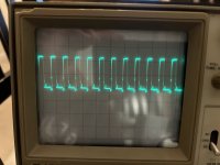
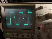
Gate and drain waveforms at 20us timebase and 5volts/div. Are the drain waveforms doubled because there are a pair of MOSFETs connected to each leg of the transformer?
Attachments
Last edited:
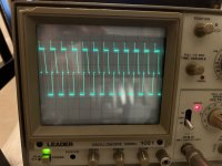
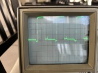
Rectifier waveforms at 10us and 10v/d. All the middle legs have either the first or second waveform depending if they are connected to leg 1 or 3 of the inductor. Why are these first two waveforms mirror images across the x axis of each other? The outer legs all have the third waveform. Again a double waveform here.
Attachments
Last edited:
When viewing waveforms, leave the scope on DC coupling (it is), set the trace to the reference line, adjust the timebase so that you have 3-4 full cycles. Adjust the vertical amplifier to use as much of the display (vertically) as possible (with the trace set to the reference).
Mirror images? They're the positive and negative outputs of the rectifiers.
Double? Not double. It's a regulated power supply and has a reduced duty cycle. Did you try lowering/varying the input supply voltage as suggested?
Mirror images? They're the positive and negative outputs of the rectifiers.
Double? Not double. It's a regulated power supply and has a reduced duty cycle. Did you try lowering/varying the input supply voltage as suggested?
Thanks for all the tips. I did set the trace to the reference as well. Ill remember to show 3-4 cycles and the amplitude tip. I unfortunately dont have a PS that can be lowered. Im using a PC PS and it only has 12v,9v and lower. I tried the 9v leads and it wouldn’t power on. Do the waveforms look correct? I thought they would be perfect square or sine waves but they have a very peculiar shape.
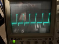
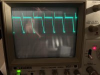
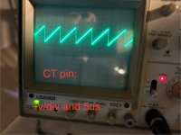
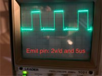
I retook the gate waveform using 5us and 2v/d.
I retook the gate waveform using 5us and 2v/d.
Attachments
Last edited:
The power supply gates are typically , roughly, square... most of the time. The drains may not be anywhere remotely square and the 'square' wave isn't always on the drain.
Those waveforms look OK. Grounding the scope probe to the source leg of the PS FETs (in this amp) might make a slight difference but if you try it, do NOT let the ground clip short to the drain. Either ground very near or solder a short piece of wire to connect the ground clip to.
Those waveforms look OK. Grounding the scope probe to the source leg of the PS FETs (in this amp) might make a slight difference but if you try it, do NOT let the ground clip short to the drain. Either ground very near or solder a short piece of wire to connect the ground clip to.
I tried very carefully to ground it to the source leg and the waveform was the same. Actually even without the ground clip connected to the pcb the waveform was the same.
I see in the schematic that the amp also has transistors in the power supply section. Can I check anything on the B-C-E legs?
I see in the schematic that the amp also has transistors in the power supply section. Can I check anything on the B-C-E legs?
Depending on the amp, the noise present (from switching) and other variables, the ground point can sometimes make a big difference, not always.
You can check them to photograph and make notes but if the waveform is OK at the gates, all is likely perfectly OK back to the output of the driver IC. Again, be careful and don't let the probe slip.
You can check them to photograph and make notes but if the waveform is OK at the gates, all is likely perfectly OK back to the output of the driver IC. Again, be careful and don't let the probe slip.
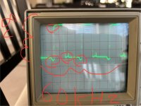
are the circuled irregularities in the gate waveform noise? In a noiseless waveform are they perfect squares? What am I suppose to analyze when looking at the gate waveform. I hope my math is right but I see that I am getting a little over 8v in amplitude and its a 60khz waveform. My input B+ voltage is 12v.
Attachments
At 5us (if the knob is in the correct position on the shaft and the timebase is set to cal) that would be 60k which would be about double what I'd expect. You can use the values on the diagram and the datasheet of the driver IC to calculate what it should be. The frequency would be for the on-board oscillator, not the frequency at the gates.
I wouldn't really call those noise but you are not likely to see anything near a perfect square wave beyond the output of the driver IC. What you look for is that the falling edge of the waveform is very nearly perfectly vertical and goes to within about 1/2v of ground.
Yes. 8v. Ideally it would be a bit higher but if it was 10v instead of 8v, it wouldn't make a difference.
Sorry for the noob question but which is the driver IC? Btw I have checked the timebase against the calibration point and the phone app function generator it’s correctly aligned.

I have read a few datasheets for PWM driver IC's trying to figure out the correct formula for calculating the frequency. The SG/LM3524 cite 1/(Rt*Ct) or 1.3/(Rt*Ct). This amp has a Ct of .0047uf and an Rt of 2kohms. Therefore these formulas give me 106khz and 138khz respectively. In your tutorial you mention TL594 and in its datasheet, it mentions a formula for a push-pull application of 1/((2*Rt)*Ct). This gives 53khz which is closer to my calculation. Not sure if I'm doing this right but I'm off to learn some more...
You're mixing oscillator frequency with output frequency. They're a factor of 2 different.
Different datasheets give oscillator frequency as 1.18/rc for the 3524
And 1.1/rc for the 594.
Different datasheets give oscillator frequency as 1.18/rc for the 3524
And 1.1/rc for the 594.
So how do I check the waveform frequency of 60khz that I saw at the gates? Is that the output frequency? Did I understand you correctly that it’s 1/2 of the oscillator frequency at the driver ic?
I would like to understand, if at all possible, where the 60khz gate frequency comes from. If I understood your previous post and amp tutorial I believe it comes from the driver IC, but maybe I'm wrong. You said earlier that you thought 60khz was too high and to check the driver IC and the diagram to figure it out. This is when I came across the driver IC's oscillator frequency formula which is derived from the values of a capacitor and resistor and I assumed this is what you meant when you said look at the IC datasheet and the diagram. Now I feel from your comments that I am misunderstanding how the driver IC's oscillator frequency is related to the MOSFETs gate frequency.
- Home
- General Interest
- Car Audio
- Soundstream Rubicon 502 with DC voltage in right channel