The 3524 and all similar ICs have an on-board oscillator. They use this as the reference for frequency. The circuit designer selects the timing resistors and capacitors that will result in the desired oscillation frequency.
That oscillator is run into a 'flip-flop' which (in this instance) acts like a divide-by-2 device/component. The flip-flop has 2 outputs and you will never have both 'on' at one time (as long as pin 13 is tied to the 5v regulator, which it always be for a push-pull supply). Those two outputs are driven into transistors which drive the output of the IC. The output of the IC (possibly through even more buffers/drivers) drive the gates of the PS FETs.
When the flip-flop divides by 2, the output frequency is cut in half (120k to 60kHz here).
The datasheet tells you this and much more. Reading the datasheets for the TL594, SG3525 and the SG3526 fill in more blanks.
Thank you Perry. I really appreciate all that you have taught me and for being so patient with me as I learn this stuff. It's really fascinating and I am truly loving it. I know I have a long way to go to fully understand how circuits and amps work but I will keep at it!
I am trying to get a deeper understanding on how power supplies work and what each component does. Your website has been an incredible source of information for me.
Unfortunately, I can't see the flash files on just one particular page:
https://www.bcae1.com/switchingpowersupplydesign/switchingpowersupplytut01.htm
The error I'm getting from ruffle is "Not enough memory left".
Unfortunately, I can't see the flash files on just one particular page:
https://www.bcae1.com/switchingpowersupplydesign/switchingpowersupplytut01.htm
The error I'm getting from ruffle is "Not enough memory left".
There is a very simple solution but no one will use it. Download and install the Safari 5.1.7 and Chromium Portable browsers and install the 4 Flash player files. These are for my site alone which is perfectly safe. The files and more details are at the following address.
https://www.bcae1.com/temp/!_READ-ME_if_you_want_to_view_the_Flash_files.htm
https://www.bcae1.com/temp/!_READ-ME_if_you_want_to_view_the_Flash_files.htm
Thanks Perry. Will give one of those browsers a shot. Back to the amp repair...
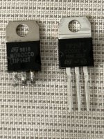
I bought some TIP142T's but due to the lack of available US inventory or slow shipping from overseas vendors I decided to give Ebay a try. I know it's not recommended because of the possibility of getting fakes. I have received them and they are dated March 2012. Markings are very different from the originals. See pics. So I'm hoping they are not fakes and just new old stock. The seller had really good reviews and communication. Any telltale signs for fakes?
I have gone ahead and hard-wired all the new TIP142T's to Q2-Q6 and the amp is working good. It plays fine at medium to medium-high volumes.
Attachments
I know you don't put much stock into the TR\LCR\ESR testers for transistors, but I have an MK-328 and here are the comparable results:
Original TIP142Ts:
hFE=0.95
Ie=9uA
Vbe=125mV
Uf=563mV
New TIP142Ts:
hFE=234
Ie=5.4mA
Vbe=1.27V
Uf=677mV
hFE, Ie and Vbe are very different values.
Original TIP142Ts:
hFE=0.95
Ie=9uA
Vbe=125mV
Uf=563mV
New TIP142Ts:
hFE=234
Ie=5.4mA
Vbe=1.27V
Uf=677mV
hFE, Ie and Vbe are very different values.
The MAR isn't likely March. It's more likely an abbreviation for the production location.
The 20 is likely 2020. The 12 is likely the 12th week.
If anyone knows definitively, correct me.
If you have extras, crack one new and one old open. Squeezing in vice from the side (at a slight angle) will pop the plastic off easily.
The bottom of page 20 of my site shows some ways to tell fakes with links to other good pages.
You can also measure the internal resistor values between terminals. Compare new to old.
To compare against the original Q2 above here are my new transistor readings:Resistance:
Q2:
B-C: 1197k
C-E: open
B-E:13.6k
Diode check (Left letter red probe - right letter black probe):
Q2:
B-C: .586
C-E: open
E-C: .451
B-E: .631
C-B: open
E-B: open
Resistance:
New Transistor:
B-C: open
C-E: open
B-E:7.6k
Diode check (Left letter red probe - right letter black probe):
New Transistor:
B-C: .622
C-E: open
E-C: .550
B-E: .684
C-B: open
E-B: open
For some reason the new transistor B-C has an open resistance but it does briefly show a number and then goes open. Much like a capacitor. The old transistors don’t do that.
As for breaking a transistor open I don’t have a vice. Any other ideas how to do it?
Last edited:
On a positive note the amp played for 2 hours at a pretty high level through components speakers without any heating or sound issues. I think next test is a low ohm subwoofer. And then Ill install them properly.
Are they all clamped to the original heatsink? OK, if they are. If not, be careful with temperature.
They are currently attached to a spackle knife. Ive been monitoring the temp and they stay room temp. The driver board transistors are the only ones getting warm on both the left and right channels. They go up to 150F.
If the outputs overheat and fail, they could cause damage to the driver board. Watch them closely.

I was playing the subwoofer at medium volume for 1-2mins and then the amp died. Not sure if it’s protection mode but the lights turn on when power is applied and then it shuts off. There was whine or hiss coming from the transformer or inductor right before it died. Nothing felt overheated. Fuses are fine. I still had the low amperage (5A) fuses installed. I measured the voltage at the ground and B+ terminal and the amp starts at 12v and quickly drops when powered on. Yet when the power supply is not connected to the amp it produces 12v fine.
Tested the resistance of the rectifier middle legs with the outer legs and no shorts. Tested all power supply transistors and no shorts. Then tested the output transistors and have a short in the new transistors. Q2-Q6 have a short (6ohms) on the C-E legs. I think I should remove them to see if they are responsible for the short.
Went ahead and removed Q2-Q6 and found the problem. One of the new transistors was shorted on C-E. What could this mean? Are they fakes or is something else causing this?
Installed a single old transistor into the Q2-Q6 bank and amp powered on fine and played music.
Last edited:
That's not a good sign. Are you 100% sure that it was flat against the metal so it couldn't over hear quickly?
- Home
- General Interest
- Car Audio
- Soundstream Rubicon 502 with DC voltage in right channel