The trigger level control is working then. And yes the trigger led was lit with both waveform. I was able to eliminate the duplicate waveform with the trigger coupling switch. It has 4 settings AC, HF-REJ, LF-REJ and DC. I noticed that the glitchyness and duplicate waveform would go away could with HF-REJ.
High frequency reject filters high frequency noise that can make the scope trigger on the wrong part of the waveform.
Find the focus control and see if you can sharpen the display. If not, the astig may need to be adjusted but it's a bit trickier to get right.
Find the focus control and see if you can sharpen the display. If not, the astig may need to be adjusted but it's a bit trickier to get right.
Focus didn’t correct it. It was already as focused as it could get. I guess it’s astigmatism you mention. For now can I just use the coupling switch to fix it?
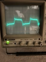
So those previous waveforms were of the audio jack of my phone sending the sine wave directly to the oscilloscope. That line was crisp. Now I hooked up my phone to the amp and the oscilloscope to the speaker terminals. Now there are these small ripples or beads that move along the waveform. It’s on both channels. Is this a problem?
So those previous waveforms were of the audio jack of my phone sending the sine wave directly to the oscilloscope. That line was crisp. Now I hooked up my phone to the amp and the oscilloscope to the speaker terminals. Now there are these small ripples or beads that move along the waveform. It’s on both channels. Is this a problem?
Attachments

There is a lot of noise. Connect the scope probes short ground lead to the non-bridging speaker terminal of the channel you're probing.
I was using an alligator clip with a long wire of about 18in. I swapped it for a probe with a short 3in wire and it solved the problem. Any recommendations on other oscilloscope tests I can run to verify it works properly?
Not really.
Calibrate the probe on the test signal.
Set the vertical amplifier var to the cal position, align the trace to the reference line, set the vertical amplifier to 5v and touch the probe to the 12v power supply to verify that the trace deflects to the actual output voltage of the 12v supply.
Calibrate the probe on the test signal.
Set the vertical amplifier var to the cal position, align the trace to the reference line, set the vertical amplifier to 5v and touch the probe to the 12v power supply to verify that the trace deflects to the actual output voltage of the 12v supply.
Thanks for that tip. It checked out fine. As did the timebase comparing it against the 1khz signal. So the only problem is that astig issue but the coupling switch fixes it. Thanks Perry for all your advice. I'll let you know how the amp behaves once I install the new transistors directly on the PCB. Should I first install the new ones hardwired to see if they work properly?
I think there was some problem on the board that was causing the problem.
The astig is similar to the focus but a bit different. It has nothing to do with triggering. If the trace is sharp, leave it as is.
The astig is similar to the focus but a bit different. It has nothing to do with triggering. If the trace is sharp, leave it as is.
When I try and show a low frequency sine way, like 50hz, which requires a very low timebase (10+ms) to show many peaks the waveform is no longer a solid image, but more like a constantly refreshing image scanning from left to right. Which make it difficult to analyze the waveform as it's slowly scanning constantly. Is this normal behavior?
I powered up an old scope I have here and the lowest I can go with a steady trace is 2ms (which is where I left my other scopes when looking at audio). Below that (5ms, 10ms...), you can't expect a steady trace. With a 50Hz sine wave, I can see the entire wave at 2ms.
As a side note, I was glad to see it power up. It was made in the 1960s and don't know how many more times it will power up before something fails.
As a side note, I was glad to see it power up. It was made in the 1960s and don't know how many more times it will power up before something fails.
Thanks for confirming that. I also just read an EEVBLOG thread saying that the older scopes (non digital storage) have a different phosphor screen that is not as persistent as the digital storage scopes. I think that's the cause. I'm not sure of the year of my model but I hope it continues turning on for years to come. I can't even find a user manual online for it. I did find the service manual.
Do you have the ground clip for the scope probe connected to the output ground of the function generator?
My apologies. I should have been more clear. The function generator is an app on my phone feeding the amp with RCAs. Im reading the square wave with the probe on the postive speaker terminal and the ground on the non-bridged negative speaker terminal.
Are you sure that the negative terminal is a non-bridging terminal?
Try a sine wave. Amplifiers aren't designed to pass square waves.
Always post the timebase and vertical amplifier settings when you post a waveform.
Try a sine wave. Amplifiers aren't designed to pass square waves.
Always post the timebase and vertical amplifier settings when you post a waveform.
Last edited:
Yes its the same speaker terminal I used before (audio ground or secondary ground) to test the light bulb with the positive being the rail voltage. The amp’s outer terminals are the bridgeable ones (L- and R+). Im using one of the inner ones, R-. I also tried excluding the amp and just putting the probes on the rca terminals coming out of my phones audio output and the same deformed square wave occurred.
Sine waves always work fine. Ill get the tinebase and amplitude for you next time I run it again.
Sine waves always work fine. Ill get the tinebase and amplitude for you next time I run it again.
Back to the topic of the amp. When I reinstall the transistors should I only replace the broken leg one with a new one or replace them all with new ones? Also how do you recommend I bend the legs on the new ones? How important is it that I bend the legs at the exact same point for all legs and all transistors? Will it affect heat transfer to the heatsink if it’s not perfect?
Replace all, preferably from the same production batch (may not be possible buying in small quantities).
See attached.
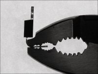
They don't have to be bent within one ten-thousandth of an inch but try to get them the same.
Some people won't grind a pair of good pliers but you can buy cheap pliers at a dollar-store or at a Goodwill type store or maybe at a flea market.
Heat transfer will generally rely on how flat the transistor lays on the heatsink. You can insert them into the holes, clamp them down, tack them in and then remove the board, check to confirm that they're flat to the board and if so, solder them in.
See attached.
They don't have to be bent within one ten-thousandth of an inch but try to get them the same.
Some people won't grind a pair of good pliers but you can buy cheap pliers at a dollar-store or at a Goodwill type store or maybe at a flea market.
Heat transfer will generally rely on how flat the transistor lays on the heatsink. You can insert them into the holes, clamp them down, tack them in and then remove the board, check to confirm that they're flat to the board and if so, solder them in.
Attachments
any fun or educational tests I can run with my oscilloscope on my amp? Tests on the power supply, pre-amp, driver, etc sections? Not to diagnose the problem in the thread, but more so to learn about amps in general.
- Home
- General Interest
- Car Audio
- Soundstream Rubicon 502 with DC voltage in right channel