@Salar. Where in the circuit are you introducing your external clock? On the servo board or on the D/A side? Just curious ?
Nowhere, nothing modified. Just hope that your mod will cure my skipping problem as well. But I have no time right now to do it.
Ok. Resonator X601 is listed in the Bill Of Material as 16Mhz but it is actually 16.9344 Mhz. The exact frequency. The odd thing is the way they synchronize it to the DAC side.
And by the way, so far things seems promising but we have to give it some more time.
The sound produced is definitely much much better.
And by the way, so far things seems promising but we have to give it some more time.
The sound produced is definitely much much better.
Modding the power supply with MKP capacitors could be tried as I suspect the high frequency response of the psu is not good enough. It is a shot in the dark, but it has a good reason.
Even if you connect an external clock, the other issues point towards the common source of problem.
Gajanan Phadte
Even if you connect an external clock, the other issues point towards the common source of problem.
Gajanan Phadte
@dacen @ilcapo
Any news? It has become cold again for some days, so i could try dacen´s mod.
What about soldering on connections leading to the laser diode?
Any risk of causing electrostatic breakdown?
Any news? It has become cold again for some days, so i could try dacen´s mod.
What about soldering on connections leading to the laser diode?
Any risk of causing electrostatic breakdown?
Last edited:
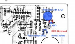
" What about soldering on connections leading to the laser diode? " I would not recommend that. I did a lot of changes to the board as I had the player apart. It might not be necessary with all of those changes. Try the simplest first. Solder a strap across D602 and connection directly to pin 2,3 IC602 is in place. Remove JW600 and connect JW602 to ground. This might do the trick for you. I have had no problems so far. The player starts every time when cold and plays music flawlessly. As you can see on my drawing I have also increased Power On Reset slightly. I have increased C697 from 3.3uF to 4.7uF just in case.
Last edited:
There is a small risk if you work on surfaces that creates static charges, so try to avoid that. And careful with the lock mechanism on the flex cable connector. Don´t pull!. Release first!
Dear dacen, I guess it is JW601 instead of "JW602"? And do the diodes D602 really need to be bypassed?
My fault, of course it is W601. You are interested in getting a solid low signal on base of Q601. If you leave D602 in circuit the base of Q601 can take any value higher than that, so yes, bypass. If this is successful for both of us I have a permanent solution for this function. That is adding a NAND gate there. What we are doing now is trying to locate the problem and verify it. (if you don´t have a NAND gate I will send you one ,74HC00)
Last edited:
Well, I did the mod (and froze m a.. off while soldering, did not heat my home
the night before), but it does not show any effect. Still having slight glitches like before, disappearung when the X5000 warms up. I am not sure if I used a proper path for JW601 but turning it 90 degrees counterclockwise and soldering to where ground connection of JW600 was should be corretct?
Added a jpeg showing the mod.
And why did Sony add D602?
All the best,
Salar
Attachments
Yes what you have done is correct. D602 is to introduce a logic high to shut down the laser during power up. That is the small time space before LDON pin 62 IC201 has control of the laser. This is just a double security to give the +5volt and the logic time to stabilize.
Well, you have to take it one step further. Do you have a spare reg. 7805 ? If you don´t send me a PM with your address and I will send you the 74HC00 and the 7805.
Well, you have to take it one step further. Do you have a spare reg. 7805 ? If you don´t send me a PM with your address and I will send you the 74HC00 and the 7805.
Last edited:
So I guess I can "unbridge" D602 again?
(Hope it was not destroyed by the heat)
Thank you very much, I can get a 7805 and 74HC00 where I live.
Spo what is the next mod?
But shouldn´t we also look for a temperature related mismatch between the sled motor and horizontal laser coil?
All the best,
Salar
(Hope it was not destroyed by the heat)
Thank you very much, I can get a 7805 and 74HC00 where I live.
Spo what is the next mod?
But shouldn´t we also look for a temperature related mismatch between the sled motor and horizontal laser coil?
All the best,
Salar
Last edited:
Leave it bypassed. No heat is generated in D602. Put in the separate voltage regulator 7805 as referred to in my drawing. Cut the track feeding the emitter of Q601 and connect the new +5volt to it. Cut the track at connector CN210 removing the old 5volt, the 12 pin connector going to the laser, pin7 VCC and connect the new 5volt to this pin. As you can see the numbering on this cable is opposite in each end, so be aware that you are on the right pin. I can only contribute to a problem that I believe might be related to my problem. If you after this still have a skipping problem it must be related to something else. These modifications you are doing are an improvement anyway. A drawing with the 74HC00 in circuit will follow in a while.
What we achieve here is a voltage to the laser with much less digital noise as none of the other circuits are connected to this one.
What we achieve here is a voltage to the laser with much less digital noise as none of the other circuits are connected to this one.
Last edited:
Hello dacen, thanks a lot!
But i did put everything back to default, ecxept 4.7µF for C697 and 10Ω for JW600 (10Ω cured the startup problem).
Would be interesting wether noiseless power supply would result in a cleaner eyepattern, Did you do any tests on this?
All the best,
Salar
But i did put everything back to default, ecxept 4.7µF for C697 and 10Ω for JW600 (10Ω cured the startup problem).
Would be interesting wether noiseless power supply would result in a cleaner eyepattern, Did you do any tests on this?
All the best,
Salar
Great... I never looked at the alignment procdures of the service manual in detail - I just knew that eyepattern/ E-F balance / clock freqiencies etc. can be measured.
Well - you can´t align anything.
No pots on the pcb. You "only" can adust mechanically the laser´s height to get clearer eyepattern and write focus/tracking auto gain data into the X5000´s memory
using YEDS-18 Test CD - which I have.
I´ll do this next...
All the best,
Salar
Well - you can´t align anything.
No pots on the pcb. You "only" can adust mechanically the laser´s height to get clearer eyepattern and write focus/tracking auto gain data into the X5000´s memory
using YEDS-18 Test CD - which I have.
I´ll do this next...
All the best,
Salar
Checked the eyepattern now, no need for skew adjustment (Page 11 in manual).
Also did writing of Focus/Tracking Auto Gain Data (Page 3 in manual) using YEDS-18 Test-CD
These are the only things a service technician could do.
No other alignments are possible.
No difference. The player still still needs to warm up to play flawlessly.
It also did not react when the lid was closed in the very beginning.
Closing/opening the lid for two or three times cured this.
The whole concept of servicing the CDP-X5000 is a little bit ridicilous.
You can measure a possible fault, but not cure it, because there are no variable resistors to turn.
All test pins are inside small connectors. Very hard to access and measure.
Harder to make a connection from a pin to ground i.e, to put the player in service mode.
Last edited:
Hello Salar,
by chance I came to this thread, I had a similar problem with my CDP XA7ES (fixed pickup) - with mine player fix was simple to plug- replug all connectors to the servo board...maybe this is link is of help (Sony CDP-XA7ES on thevintageknob.org) scroll down to <talk> and see the answer regarding transport...
voltage instability at the spindle driver chips beause of too the high resistor for the reference zener diode in the negative voltage of digital power supply..
in my player this bug has been fixed by sony...
I have not gone through all this thread, but I can imagine a leaky capacitor (for instance right at the laser there is usually 100yF or so to bypass the laser power control transistor BE junction)...good luck, Philipp
Well this is most, most interesting. Have modified my X5000 with a nand gate and it is up and running, but I suspected that the problem still persist. I have the service manual for the CDP XA7ES. Send me a PM and I will send it. Too big for attaching to the thread. The digital solution seems very identical. Hmm.
Last edited:
Very interesting. I would like to have the SM as well to make comparison between CDP XA7ES and CDP-X5000.
- Home
- Source & Line
- Digital Source
- Sony X5000 troubleshooting