It doesn't matter what kind of dielectric is being used (ceramic, plastic foil...), what matters is that it's a Class X capacitor when it's connected across the lines (neutral to phase)!
Capacitor Characteristics
Capacitor Characteristics
It's hard to get a picture of, but the cap says 3n3 J400VL on top. I'll rummage through my mouser orders to see if I can find the exact spec sheet. Bound to be in there somewhere.
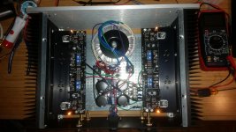
I've got my front end up to 1.5V ( same process as getting my BA-3 FE preamp set up ), with ground to T18 as close to zero as I can get it. Also rechecked and adjusted G to T16 and G to T17 to keep it dialed in for my vfets.
One thing...this is my first time using single turn pots. I've read many jokes here about getting them in the right spot, but getting G to T18 close to 0 seemed to require a combination of screw driver weight, rotating it, and some voo doo. Is this normal? Seems to stay put once set, but I worry that moving the amp around could jar the finicky pots. Unnecessary paranoia?
Time to put the vfets in?
Last edited:
Single turn pots have fewer parts and have better long term stability.
See my (and other's) opinion as stated in posts #1763 and #3067 in the Sony VFET Amplifier pt2 thread.
Sony VFET Amplifier Part 2
Sony VFET Amplifier Part 2
What you can and should do is to slightly tap the pot's housing with the screwdriver to promote the pot to release any residual mechanical stress of the moving parts (pot...release stress, haha). That way you can see any changes in the setting while the meters are still attached.
One thing...this is my first time using single turn pots. I've read many jokes here about getting them in the right spot, but getting G to T18 close to 0 seemed to require a combination of screw driver weight, rotating it, and some voo doo. Is this normal? Seems to stay put once set, but I worry that moving the amp around could jar the finicky pots. Unnecessary paranoia?
Without the Vfet installed the currents in the amp are all pretty low, so small changes in resistance will have a big effect on draw - hence why the pots seems super sensitive. With the circuit running at spec, the sensitivity of the pots will lessen somewhat.
Without the VFETs installed there is also no feedback, since the loop from output to input is not closed. With the VFETs in place the feedback loop is closed and things start to get interesting 🙂
Without the Vfet installed the currents in the amp are all pretty low, so small changes in resistance will have a big effect on draw - hence why the pots seems super sensitive. With the circuit running at spec, the sensitivity of the pots will lessen somewhat.
That makes sense. Thank you 🙂
I fired it back up this morning to warm up and everything settled back into place where I left it yesterday, with offset bouncing around between +- 75mv for both channels.
To get offset right yesterday I would purposefully slightly overshoot whatever direction I was turning the pot so it could settle back to the value I was aiming for, so tapping the pot to relieve stress also makes sense. I gave them each a small thud this morning just to be sure. Everything stable 😉
Going to pull it back apart and get the vfets in now.
Almost forgot....Thank you guys!
Last edited:
I finally had the chance to give my copy of the diyaudio sony vfet a good listen. I burned it in for about 10 hours in my garage fist, and compared to my much loved M2 using single full range backloaded horn speakers. The M2 is a pretty cool running amp for a Pass class A amp, but the VFET is even cooler, barely gets warm. The first impression that I got swapping in the VFET for the M2 and playing the same music was that it seemed more illuminated, maybe lower noise floor or what not, but it seemed easier to hear the subtle details. The overall balance was similar but the VFET has distinctly better control of the base, more of a F6 type grip on the speakers, it has a higher damping factor than the M2 so that might figure into it. So basically sounds great, better base, more detail subjectively than M2. Does it sound better ? I don't know, it is the same dilemma with all Pass amps, they all sound really good, but a little different. That is why you need to build so many of them.
Hi all, I'm just a bit curious - one of my VFETS is labelled 201 - for a 2sk82 (from the official DIYAUDIO buy) and that seems quite high? If I follow the document properly, that means an initial bias point of 20.1V + 1V = 21.1V?
For comparison, it's matched partner is marked 170, making for a 18V initial bias point.
I just want to sanity check that before I bias up the irreplaceable parts...
For comparison, it's matched partner is marked 170, making for a 18V initial bias point.
I just want to sanity check that before I bias up the irreplaceable parts...
Last edited:
Those numbers are not values of measurement, but id number of the VFET. Don't get confused with the two.Hi all, I'm just a bit curious - one of my VFETS is labelled 201 - for a 2sk82 (from the official DIYAUDIO buy) and that seems quite high? If I follow the document properly, that means an initial bias point of 20.1V + 1V = 21.1V?
For comparison, it's matched partner is marked 170, making for a 18V initial bias point.
I just want to sanity check that before I bias up the irreplaceable parts...
Cheers
Haha! Champion, thank you! The K parts have had the vds rubbed almost completely off...now you say it I can just see an 88 on one.
Woohoo! Thanks 🙂
Woohoo! Thanks 🙂
Mains transformer
Hello to all, can someone enlighten me on the minimum power rating of the transformer?
Hello to all, can someone enlighten me on the minimum power rating of the transformer?
Dissipation is P=U*I=2*28V*1A=56W per channel, so about 112W in total for an amp. The transformer should be rated about three times that, so you're looking at 300VA. Better make it 400VA, the difference in price should be negligible. Search the thread, it's been discussed numerous times.
Power line filter
I have some of these 6A 120v power line filters 6EQ1 by TE: http://www.mouser.com/ds/2/418/NG_CD_6EQ1_H-1258746.pdf
They are an RFI filter designed for SMPS supplies, but would it be beneficial to the diy vfet amp. Got my boards stuffed and I'm about to start construction.
Thanks
I have some of these 6A 120v power line filters 6EQ1 by TE: http://www.mouser.com/ds/2/418/NG_CD_6EQ1_H-1258746.pdf
They are an RFI filter designed for SMPS supplies, but would it be beneficial to the diy vfet amp. Got my boards stuffed and I'm about to start construction.
Thanks
Pass DIY Addict
Joined 2000
Paid Member
I don't see how it can hurt. Each of my amp builds gets a one of these (or something similar) built into an EIC power inlet. I kind of view it as standard procedure and judging by the pictures posted, so do lots of other people.
Go ahead and use it!
Go ahead and use it!
- Home
- Amplifiers
- Pass Labs
- Sony vFET Illustrated build guide