^ Fair enough... 🙂
Trying to think of what else may be interesting to look at...
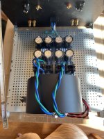
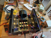
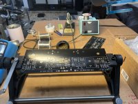
Someone had asked about the toroid mounting. It's a simple bracket from a local hardware store + the Antek steel case. To me, it's a wonderful solution. The big Antek cases are a bit pricey, but the mount is very stable, and the EM isolation => reduction in noise is measurable. I haven't rotated a toroid for lowest noise in several builds. I like mounting vertically up front when space allows. The only downsides are that those cases are pretty heavy and they add diameter and height. In a tight build where the benefits of the EM shielding are of most benefit... space is a consideration. This is in a 5U and it barely fits for height. I could mount it lower, of course.

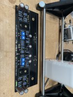
Another person should have been mentioned. I think a lot of people are using Randy's PSU boards and other nifty add-ons. He did a fantastic job on the CL-60 / cap boards. They make for a much tidier build. That's it to the right of the mount in the picture.
Note - Mains wiring is not subject to any sharp chassis edges in final build. 😉

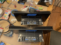
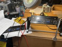
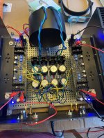
Nope, 3 DMMs just wasn't enough. Also, for those that don't have them in their bag... I strongly, strongly recommend getting some little J-type clips for your DMMs. They're relatively inexpensive, and to me, they're invaluable. I got a few originally with my DMMs, and I bought extras online for ~3USD per piece. I leave them (in this case 10 pairs) hooked up, and I move DMMs between them. That way, the risk of nudging something or shorting something unintentionally when moving probes is mostly mitigated. Also, it makes it to where you don't accidentally measure off the wrong pad / lead after moving (cough), which can easily happen with multiple measurement points. If you forget (cough) to raise a resistor for ease of measurement with alligator clips, they get into even the tightest of spaces... I think this pic was right after powering on for the "final" check / warm up cycle before moving putting it in the system. Back to front ... FE offset, FE bias voltage #1, FE bias voltage #2, Speaker offset, OS bias voltage. For me, it started up roughly here each time; and over about an hour FE voltages increased to 1V5, OS measurement (across R32) decreased to 103mV and offsets remained pretty stable.

Here is an example of the clips. These are poorly built, IMO, and I re-solder the wire to the clip periodically, but they're hard to beat for the price.
https://www.amazon.com/dp/B073SP3G6D?psc=1&ref=ppx_yo2ov_dt_b_product_details
And... a montage of pics taken throughout...
Some pics that might seem random...


Various stages of the build... in attachments.
Trying to think of what else may be interesting to look at...
Someone had asked about the toroid mounting. It's a simple bracket from a local hardware store + the Antek steel case. To me, it's a wonderful solution. The big Antek cases are a bit pricey, but the mount is very stable, and the EM isolation => reduction in noise is measurable. I haven't rotated a toroid for lowest noise in several builds. I like mounting vertically up front when space allows. The only downsides are that those cases are pretty heavy and they add diameter and height. In a tight build where the benefits of the EM shielding are of most benefit... space is a consideration. This is in a 5U and it barely fits for height. I could mount it lower, of course.
Another person should have been mentioned. I think a lot of people are using Randy's PSU boards and other nifty add-ons. He did a fantastic job on the CL-60 / cap boards. They make for a much tidier build. That's it to the right of the mount in the picture.
Note - Mains wiring is not subject to any sharp chassis edges in final build. 😉
Nope, 3 DMMs just wasn't enough. Also, for those that don't have them in their bag... I strongly, strongly recommend getting some little J-type clips for your DMMs. They're relatively inexpensive, and to me, they're invaluable. I got a few originally with my DMMs, and I bought extras online for ~3USD per piece. I leave them (in this case 10 pairs) hooked up, and I move DMMs between them. That way, the risk of nudging something or shorting something unintentionally when moving probes is mostly mitigated. Also, it makes it to where you don't accidentally measure off the wrong pad / lead after moving (cough), which can easily happen with multiple measurement points. If you forget (cough) to raise a resistor for ease of measurement with alligator clips, they get into even the tightest of spaces... I think this pic was right after powering on for the "final" check / warm up cycle before moving putting it in the system. Back to front ... FE offset, FE bias voltage #1, FE bias voltage #2, Speaker offset, OS bias voltage. For me, it started up roughly here each time; and over about an hour FE voltages increased to 1V5, OS measurement (across R32) decreased to 103mV and offsets remained pretty stable.
Here is an example of the clips. These are poorly built, IMO, and I re-solder the wire to the clip periodically, but they're hard to beat for the price.
https://www.amazon.com/dp/B073SP3G6D?psc=1&ref=ppx_yo2ov_dt_b_product_details
And... a montage of pics taken throughout...
Some pics that might seem random...
I always test every piece, and for really important pieces, I usually take a photo of case markings ... especially anything precious. I have to take photos anyway b/c I can't read the package markings w/o magnification. Then I sticker them or mark them some way.
Dim bulb / Variac - Safety first. Note Variac use after VFETs are installed is not per the norm. I also used it to keep mains a bit lower before I had enough bias on the output stage to result in the PSU sagging below 32V. My 1A fuse survived throughout, but I had a soft start / CL-60s in addition to the Variac. Had to move locations at this stage... WAF lowered significantly.
Various stages of the build... in attachments.
Attachments
-
 IMG_3509 copy.png1.6 MB · Views: 219
 -
 IMG_3510 - Copy.jpg342.1 KB · Views: 230
 -
 IMG_3519 copy.png5.2 MB · Views: 244
 -
 IMG_3497.jpg631.8 KB · Views: 225
 -
 70665046252__D74099C4-2F58-4B3D-8CE1-2BD07FB4EB66.jpg470.8 KB · Views: 202
 -
 70666141744__7AC64675-BE6E-4A74-BA6B-F4B492195D25.jpg513.4 KB · Views: 200
 -
 70683594185__CE68B61E-DF45-44C4-8309-8A4CA2A39A39.jpg451.6 KB · Views: 191
 -
 70820692858__200DAC03-FBBB-4F0C-BE02-4983305AD934.jpg519.7 KB · Views: 207
 -
 70822555390__CAC8A6CA-5214-4042-B94D-B679AC495850.jpg595.8 KB · Views: 198
 -
 IMG_3494.jpg479.7 KB · Views: 215
Last edited:


Pass DIY Addict
Joined 2000
Paid Member
Nice build! Thanks for the details on the vertical transformer mounting. I'm likely to use that approach with my SissySIT build. Have to wait until I get transformers in hand to see how much room they take up.
Thank you!now, that's proper Fugly!
even without "done and closed" pic
I have been a very lazy Greedy Boy. I haven't customized a front panel yet for any of the builds. At this point, it looks like a stock photo for a 5U/400. I need to have physical beauty to align with the sonic beauty. 🙂. Modushop's chassis are beautiful and functional as-is, but Papa amps deserve some artwork...
I'll have to work on that...
Better late than never! This project slumbered underneath my desk until I finally had an uninterrupted week to dedicate to its assembly and testing. The only customization required was sending the heatsinks to a machine shop to mill flat. They weren't even close to flat. One was warped like a taco, the other like the letter "W". That's why they look shiny in the pictures.
Wow! Thanks Nelson, for such a great sounding amplifier. This one is even spookier than my J2 in its holographic soundstage. I've finally found an amp that does the slot loaded OB, with Lowther PM6C, justice!
Oh, and thanks for my losing another night's sleep staying up way too late revisiting my favorite albums and files listening to previously unheard subtleties and details in their recordings! 🙂
Thanks! When I won the lottery for the opportunity to buy the kit I remember thinking it was something pretty special and that it deserved special treatment. 🙂
@ItsAllInMyHead
Patrick, very nice build. With the 400mm deep chassis how cold are your heatsinks?
Best,
Anand.
Patrick, very nice build. With the 400mm deep chassis how cold are your heatsinks?
Best,
Anand.
I'm not Patrick, but I'll answer anyway. 🙂
They are quite warm, but not quite as hot as a First Watt amp. I'd say just about perfect.
The only issue I've had was eliminating a very faint hum caused by the position of the transformer. I rotated it until it was almost completely gone. You have to put your ear practically on the speaker cone to hear it. I guess the Antek shielding doesn't work that well.
For those who might be interested in building this amp and plan to attend BAF, I'll be sending down an original 'essential kit' for BAF fundraising, along with all parts necessary for stuffing the PCBs, including the NOS Toshiba jfets and small mosfets.
Thank you!@ItsAllInMyHead
Patrick, very nice build. With the 400mm deep chassis how cold are your heatsinks?
Best,
Anand.
No, but I am 🙂I'm not Patrick... 🙂
@poseidonsvoice - 5U/400 - They're 39C at the warmest spot on the sinks in a 23C room. I used that chassis because I had it, and it gave me a bit more room to work.
@Dennis Hui, I plan to bring mine to exhibit in the Pass room.
Hearing it in person should encourage some lively bidding on your extremely generous donation to BAF!
Hearing it in person should encourage some lively bidding on your extremely generous donation to BAF!
Regarding the "faint hum" referenced in post #1390, last week I flipped and slightly rotated the transformer to achieve a silent, "black" background. All is perfect now! Now I know not to trim transformer leads before fine tuning. Now my nice and neat wiring is a little less so in that area. 😳
I have to say, this is now one of my favorite amps, right up there with my SIT 2. I'm running my OBs with the SIT 2 on the bottom and the Sony VFET on the Lowthers.
Nelson, your designs never cease to amaze me! ❤️ 🍷 🥂
I have to say, this is now one of my favorite amps, right up there with my SIT 2. I'm running my OBs with the SIT 2 on the bottom and the Sony VFET on the Lowthers.
Nelson, your designs never cease to amaze me! ❤️ 🍷 🥂
For those who wants to build this amp but won't be at BAF, I also have available a 'spare parts kit'
( https://www.diyaudio.com/community/...-sony-vfet-push-pull-amp.402515/#post-7433610 )
with proceeds going to BAF.
If this doesn't sell, I'll send it down to Tom for BAF as well.
( https://www.diyaudio.com/community/...-sony-vfet-push-pull-amp.402515/#post-7433610 )
with proceeds going to BAF.
If this doesn't sell, I'll send it down to Tom for BAF as well.
With an amp on display and one for auction...
I agree with @WBS wholeheartedly. This is one amazing amplifier. In other threads some may have seen my adventures in learning how to do some proper measurements. I did a few measurements on my iteration of this amp, and I admit that some of my preconceived notions (biases) were confirmed, and one was perhaps shattered...
The measurements (hopefully) don't reveal anything new or exciting to any of you, but I hadn't read the article since before building the amp, and clearly at least one my biases kept me from remembering an attribute that some find important to sonic bliss. I thought the distortion was 2nd harmonic dominant. It is 3rd. The article shows the same. My preconceived notions are shattered. Just kidding. I adore the M2x also. I've also set up my BA-3 to be even 2nd and 3rd. In my case, 3rd starts to creep higher as power increases, and I love that amp.
Without a doubt, my measurements differ from those in the article. I'm not sure if I should have read it again before doing the measurements or not... I'll stick with no... One key thing. The article shows the distortion testing at 500 Hz. I'm not sure why... and I don't think it should matter too much, but I did mine at the more typical 1kHz.
My build was with a "standard" CRC PSU with a typical Antek 400VA 22V transformer. No dual mono or anything "special". My build includes the "feedback". I didn't include a switch or anything like that to toy with it.
A few things that I had in my notes that were confirmed in the article.
1 - It behaves remarkably similar from a distortion standpoint regardless of load. This is in contrast to all the Alephs of mine that I tested that all show higher distortion at the same power output with lower impedance loads. If lower distortion at a particular power output is your thing... you'll love 16ohm speakers with an Aleph... this amp doesn't seem to care (to a point).
2 - I haven't measured a lot of amplifiers (clearly), but the VFET has the lowest distortion of any of my DIY amps that I've measured up to clipping. Most (if not all) of the amplifiers I've tested reach 1% THD prior to or right around the time I can visually notice the clipping of the waveform. The VFET stays below 1% THD up to clipping.
3 - I admit that I've had to make up my own language around describing harmonic profile behavior, but in the FFTs, the 3rd harmonic dominates. This stays consistent at either load I ran up through the usable power range of the amp. The overall 'profile' doesn't shift with load or power output.
Anyway... here is a selection of the measurements I did. I'm glad I built and loved it before I did the measurements. I admit with all the talk of negative 2nd etc. it may have biased me away from this design. When in fact... I'm going to tweak my BA-3 back and forth to see what I can learn further about my preferences.
Per usual... I'll share anything, but everyone should beware that I'm not an expert ... I've goofed measurements before, and I'll goof them again. With that said, the trends are strong enough, and I did replicates, so this should be pretty reliable.

In the Power vs. THD - it's pretty easy to see where the amp starts to clip from either a voltage or current limiting standpoint.
The software I'm using allows me to export the data. If I can, for some future measurements I'm going to change the X-axis to Output Voltage (Vrms). Then I may do one with Output Current (A). I realize it's the same curves, only shifted, but I think it would be interesting to look at. I'm not really interested in the distortion % or the power output after the amp begins to clip.
Which brings us to...

It shows a really nice symmetrical clipping. Even when I zoom in using a digital display, it's tough to catch the "precise" voltage level of clipping, so I bump it up and down until it's quite clear. I'm not interested in the difference of a Watt or two at clipping levels.

It's pretty easy to see from the two traces that the wave is nice and clean at ~33Vpp / 11.75Vrms / 17.3W @8R and that it's cut off at 12V2rms (I didn't put in the markers, but you can back-calculate as needed). That behavior is also easy to see in the PWR vs. THD chart where the distortion slope changes noticeably.
And at 4R

Exactly as the article shows, the 'negative'? half of the waveform is clipped first. I showed it right around 10.6Vrms => 28W @ 4R => ~30Vpp => 2A6. That's pretty close to the 3A from the article.

Nice and clean at 26W. This is also shown in the power vs. THD chart.
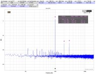
Here's a couple FFTs and what the residual looks like. Note - the residual / distortion profile is consistent (within reason) throughout the power band and regardless of load. The residual plot below was done at ~10W @ 8R because at lower power the distortion is so low that the software doesn't get enough samples for a smooth curve (I think)... The trend is easy to see through the power band, but because the voltages are comparatively low... it looks like a mess at lower power.
8R 1 and 10W


4R 1 and 10W

And a representative shot of the residual...

As with anything I put out... It really needs to be said and repeated... I'm new to this and learning. So, if you REALLY want to know how it performs, get the kit Dennis has available for auction, build it, and measure it. Mainly, just listen to it... WBS is graciously bringing theirs to audition. Check it out.
I'd be shocked if anyone doesn't LOVE IT!

I agree with @WBS wholeheartedly. This is one amazing amplifier. In other threads some may have seen my adventures in learning how to do some proper measurements. I did a few measurements on my iteration of this amp, and I admit that some of my preconceived notions (biases) were confirmed, and one was perhaps shattered...
The measurements (hopefully) don't reveal anything new or exciting to any of you, but I hadn't read the article since before building the amp, and clearly at least one my biases kept me from remembering an attribute that some find important to sonic bliss. I thought the distortion was 2nd harmonic dominant. It is 3rd. The article shows the same. My preconceived notions are shattered. Just kidding. I adore the M2x also. I've also set up my BA-3 to be even 2nd and 3rd. In my case, 3rd starts to creep higher as power increases, and I love that amp.
Without a doubt, my measurements differ from those in the article. I'm not sure if I should have read it again before doing the measurements or not... I'll stick with no... One key thing. The article shows the distortion testing at 500 Hz. I'm not sure why... and I don't think it should matter too much, but I did mine at the more typical 1kHz.
My build was with a "standard" CRC PSU with a typical Antek 400VA 22V transformer. No dual mono or anything "special". My build includes the "feedback". I didn't include a switch or anything like that to toy with it.
A few things that I had in my notes that were confirmed in the article.
1 - It behaves remarkably similar from a distortion standpoint regardless of load. This is in contrast to all the Alephs of mine that I tested that all show higher distortion at the same power output with lower impedance loads. If lower distortion at a particular power output is your thing... you'll love 16ohm speakers with an Aleph... this amp doesn't seem to care (to a point).
2 - I haven't measured a lot of amplifiers (clearly), but the VFET has the lowest distortion of any of my DIY amps that I've measured up to clipping. Most (if not all) of the amplifiers I've tested reach 1% THD prior to or right around the time I can visually notice the clipping of the waveform. The VFET stays below 1% THD up to clipping.
3 - I admit that I've had to make up my own language around describing harmonic profile behavior, but in the FFTs, the 3rd harmonic dominates. This stays consistent at either load I ran up through the usable power range of the amp. The overall 'profile' doesn't shift with load or power output.
Anyway... here is a selection of the measurements I did. I'm glad I built and loved it before I did the measurements. I admit with all the talk of negative 2nd etc. it may have biased me away from this design. When in fact... I'm going to tweak my BA-3 back and forth to see what I can learn further about my preferences.
Per usual... I'll share anything, but everyone should beware that I'm not an expert ... I've goofed measurements before, and I'll goof them again. With that said, the trends are strong enough, and I did replicates, so this should be pretty reliable.
In the Power vs. THD - it's pretty easy to see where the amp starts to clip from either a voltage or current limiting standpoint.
The software I'm using allows me to export the data. If I can, for some future measurements I'm going to change the X-axis to Output Voltage (Vrms). Then I may do one with Output Current (A). I realize it's the same curves, only shifted, but I think it would be interesting to look at. I'm not really interested in the distortion % or the power output after the amp begins to clip.
Which brings us to...
It shows a really nice symmetrical clipping. Even when I zoom in using a digital display, it's tough to catch the "precise" voltage level of clipping, so I bump it up and down until it's quite clear. I'm not interested in the difference of a Watt or two at clipping levels.
It's pretty easy to see from the two traces that the wave is nice and clean at ~33Vpp / 11.75Vrms / 17.3W @8R and that it's cut off at 12V2rms (I didn't put in the markers, but you can back-calculate as needed). That behavior is also easy to see in the PWR vs. THD chart where the distortion slope changes noticeably.
And at 4R
Exactly as the article shows, the 'negative'? half of the waveform is clipped first. I showed it right around 10.6Vrms => 28W @ 4R => ~30Vpp => 2A6. That's pretty close to the 3A from the article.
Nice and clean at 26W. This is also shown in the power vs. THD chart.
Here's a couple FFTs and what the residual looks like. Note - the residual / distortion profile is consistent (within reason) throughout the power band and regardless of load. The residual plot below was done at ~10W @ 8R because at lower power the distortion is so low that the software doesn't get enough samples for a smooth curve (I think)... The trend is easy to see through the power band, but because the voltages are comparatively low... it looks like a mess at lower power.
8R 1 and 10W
4R 1 and 10W
And a representative shot of the residual...
As with anything I put out... It really needs to be said and repeated... I'm new to this and learning. So, if you REALLY want to know how it performs, get the kit Dennis has available for auction, build it, and measure it. Mainly, just listen to it... WBS is graciously bringing theirs to audition. Check it out.
I'd be shocked if anyone doesn't LOVE IT!
Attachments
Last edited:
Pass DIY Addict
Joined 2000
Paid Member
Awesome analysis and thanks for sharing the graphs. It's quite a nice amp! What software did you use to make your measurements? I've just been using an old analog scope that was gifted to my by an electrical engineer before he retired. It looks like your analysis provides a good deal of data.
Another person should have been mentioned. I think a lot of people are using Randy's PSU boards and other nifty add-ons. He did a fantastic job on the CL-60 / cap boards. They make for a much tidier build. That's it to the right of the mount in the picture.
Beautiful build and great suggestions, but who is this "Randy" to whom you are referring? Those boards look like they'd be very useful.
- Home
- Amplifiers
- Pass Labs
- Sony vFET Illustrated build guide