Greetings,
I hope I've posted this in the right place, if not - please move to the appropriate location.
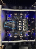
A couple of weeks ago I saw an amp listed on the goodwill auction site as "unbranded amp". I recognized the chassis as I've built projects from this store before and realized it most likely contained a Pass clone. I won the auction and had it shipped. In the meantime life goes on and I went into the hospital for a major surgery. I got out of the hospital today and finally got a chance to open the box and chassis. I was really surprised to find a Pass Sony VFET amp inside as you can imagine. I've been wanting to build a pass clone for a long time and have browsed the pages over and over many evenings.
This brings me to my main question. What do I need to do to determine if this amp is whole and functioning? I wanted to ask here first as this is the community with specific knowledge of the amp. I'm not a total newbie having built tube amps in the past, but with the scarcity of the vfets, don't want to take a chance with this amp. Thank you in advance for any knowledge you may impart.
Yes, on the one hand I know at this point I'm extremely lucky. On the other hand, if you know what a Whipple procedure is - that's what I just had done in the hospital.

I hope I've posted this in the right place, if not - please move to the appropriate location.
A couple of weeks ago I saw an amp listed on the goodwill auction site as "unbranded amp". I recognized the chassis as I've built projects from this store before and realized it most likely contained a Pass clone. I won the auction and had it shipped. In the meantime life goes on and I went into the hospital for a major surgery. I got out of the hospital today and finally got a chance to open the box and chassis. I was really surprised to find a Pass Sony VFET amp inside as you can imagine. I've been wanting to build a pass clone for a long time and have browsed the pages over and over many evenings.
This brings me to my main question. What do I need to do to determine if this amp is whole and functioning? I wanted to ask here first as this is the community with specific knowledge of the amp. I'm not a total newbie having built tube amps in the past, but with the scarcity of the vfets, don't want to take a chance with this amp. Thank you in advance for any knowledge you may impart.
Yes, on the one hand I know at this point I'm extremely lucky. On the other hand, if you know what a Whipple procedure is - that's what I just had done in the hospital.

Wow, a very lucky find, and a great amp. I have one and love it. If your luck holds out it will be in working condition. There is a startup tutorial available here which gives instructions and allowable voltages at the various test points on the amp boards. As a start you might want to consider powering it up and checking that the test points jive before risking speakers. I'm sure the kind and knowledgeable gurus here will help if you run into problems.
glad to read that you're well and fine, out of hospital
wish you speedy recovery
amp - it seems it is complete and in nice shape
so, leap of faith, connect some preamp to it and power it up
hopefully you have DMM, fist check that there is no DC on outputs, and - if good - connect speakers
wish you speedy recovery
amp - it seems it is complete and in nice shape
so, leap of faith, connect some preamp to it and power it up
hopefully you have DMM, fist check that there is no DC on outputs, and - if good - connect speakers
AWESOME!!
isn't it wonderful that someone did not dump a metal box at the recycling center for $2 but gave it to goodwill and this VFET had another chance to live? What a story 🙂) This post makes me wonder how much valuable items, how many thoughtful creations are being abandoned without thought. I bet 1 of 50 amps gets taken to goodwill and 49 to the dump.
isn't it wonderful that someone did not dump a metal box at the recycling center for $2 but gave it to goodwill and this VFET had another chance to live? What a story 🙂) This post makes me wonder how much valuable items, how many thoughtful creations are being abandoned without thought. I bet 1 of 50 amps gets taken to goodwill and 49 to the dump.
I'd hit like on all of these posts but think I'm too new to do so. I appreciate all of the responses.AWESOME!!
isn't it wonderful that someone did not dump a metal box at the recycling center for $2 but gave it to goodwill and this VFET had another chance to live? What a story 🙂) This post makes me wonder how much valuable items, how many thoughtful creations are being abandoned without thought. I bet 1 of 50 amps gets taken to goodwill and 49 to the dump.
PJN - I will go through and check the test points.
Zen Mod - thank you for the kind words. I will connect a pre and check for DC on the outputs (I do have a DMM) so I don't destroy my speakers (also DIY) and continue my leap of faith here.
nicoch58 - wish I could make it there but it isn't in the cards this year - hopefully some day
noviygera - you're right and I wish I could thank that person profusely. I thought at the least I would have a chassis to build an amp from. The price I purchased at was a deep discount on the chassis. That may still be the case here and if it is I won't be disappointed. Just a stroke of luck.
This may take a day or two for me to get to but I'll be sure to post my results here. Thank you all again.
Whipple? Wishing you a speedy recovery.
As ZM wrote, the amp looks to be in good condition and I think a lot of care went into its construction. There weren't that many of these kits back in the day and I wonder about the builder/previous owner. Perhaps we've even seen this amp somewhere in this thread.
Leap of faith of power up to check for DC offset and then verify the bias by measuring the voltage across R32 (0.1 ohm resistor). You should see about 0.1V there. Obviously no speakers attached during these initial tests.
Let things stabilize a bit. Unless the DC offset is quite high (say over 100mV) or the R32 voltage is way off then I would not attempt adjustments, as some of them can be tricky, especially with the vfets in place.
Have fun.
The amp looks really well built, yeah. With a bit of luck it'll work right out of the box.
Regarding any necessary adjustments, the single turn potentiometers used in that build offer great long term stability for the bias settings, but they're mindbogglingly sensitive. If you find yourself in need of redoing the bias procedure, start with the tiniest amount of turning the pots (sub-millimeter adjustments, just going past stiction). All settings interact with each other, and will take some time to settle (put the lid on to reach thermal equilibrium).
If the settings are way off, removing R27 and R28 will leave Q7 and Q8 turned off, that way no current will pass through the VFETs while twiddling with the pots to get the test points back up/down to spec.
So today was the day! First I'd like to thank everyone who replied as your replies were all helpful.
I looked at the build guide and verified both bias and dc offset as suggested. I then took a leap of faith and hooked it up. I'm only about 45 minutes in but it sounds great. It's a very revealing amp, more than the Adcom GFA-555 it replaced. That may not be a tall task for this amp but good news for me in any case. I may run some further checks tomorrow or may just permanently install it in the rack depending on how things go tonight. It also has enough oomph to drive the Bagby Solstice speakers I built. Good news all around.
Thanks again, hope to converse with you all on a future project.
Congrats! This must have been the easiest and most cost-effective path to get a Pass Sony VFet push-pull amp!
Just extremely lucky - really no other words for it. Thank you.Congrats! This must have been the easiest and most cost-effective path to get a Pass Sony VFet push-pull amp!
Some say, better late than never. I agree.
It must be said that the people in this community never cease to amaze me with their generosity both in sharing their knowledge and in this particular situation... a Sony VFET kit. I got a surprise PM offering me the kit, and I graciously accepted. It immediately leapt to the top of my mountain of projects. Home maintenance, golf, cycling and and all other activities took a back seat. As a result, I think a few of my long-neglected PCBs are mounting an insurrection due to negligence, I'll never shoot 70, ride in the Tour, or win lawn of the year, but... it was worth it.
The build took me a bit longer than expected, but it mostly went off without a hitch. There was an 'incident' involving a broken standoff in the heatsink from the donor chassis. I invented a few new curse words, but that was the extent of unexpected issues; unless you count spending 2 hours looking for a non-existent short during initial testing. I was charging my PSU caps with my DMM. I figured it out, but ... DOH!
I was meticulous in following Papa's directions, and I had read this thread and the previous thread several times taking notes along the way. @Rodeodave your early post re: using 5 meters per channel and watching for interactions was perhaps the most valuable bit of information for me. I was trying to do it with 3 meters at first, and I was going batty. Once I had them all connected at once and could see in real time how much the input bias affected both the FE offset and the output offset etc. etc. and how volatile it 'seemed' ... but it really wasn't ... it all went smoothly and steadily. Had I started by following that sage advice, I likely would have saved about 8 hours.
I ended up (once at stable temps and in the chassis) with <5mV of offset at the output and <20mV of offset for the FE with about 103mV across R32 for both channels. I dialed them both a bit finer on the bench... but as others have stated, it drifts a bit. I decided that I cannot obsess over it. I monitored it over 12 hours from initial turn on to reaching equilibrium and beyond with one tiny tweak, and I'm pleased. I'll continue to check it once a day until I tell myself to just leave it in peace.
Onto the good stuff...
Once I hooked it to 'real' speakers, I Let There Be Rock. The air guitar commenced along with some drums and horrible singing. Then, Chris Cornell's rendition of Nothing Compares 2 U live in studio left me verklempt. To see how it flexed on some delicate music with extension, Bela's famous Cosmic Hippo tiptoed and stomped its way around the room. SRV had me tapping my toes, playing more air guitar, and mashing the keys on my imaginary piano as I took a Look at Little Sister. I took a deep breath for the last, and the most dangerous test. How would Alisson Krauss be portrayed? Would she have that almost indescribable presence of an angel, or would she be cast as a screaming banshee hell-bent on tearing my ears off? I went Down to The River to Pray with the angel.
It would be an understatement to say that I'm thrilled with how this amp sounds in my system. To steal a Zen Mod saying... it definitely has a spooky factor, but it can absolutely rock too.
Pic attached. I haven't swapped out the temporary input wiring yet. I meant to do that before I heated it back up for the last time on the bench, but I forgot... and I couldn't wait to see what it sounded like.
Lastly - Thank you, Dennis! Quite simply put; it's an incredible amplifier. 🙂 🙂 🙂 🙂 🙂
Attachments
Congratulations on your build. It is an incredible sounding amp and my favorite out of my stable of Papa clones.
I have put my VFET amp for sale - https://www.diyaudio.com/community/threads/sony-vfet-amp-boards-papa-group-buy.399984/#post-7374838
I do not have a price for this, hence posted as accepting offers.
Thanks
I do not have a price for this, hence posted as accepting offers.
Thanks
This is also my favorite amp as it's push-pull, not as hot as the N or P channel single ended VFET.
Of course, in terms of sound SE VFET is still king in all frequency range.
Once thermal provision are correct these NP designs are rock solid!
These are the smallest environmental footprint one can get for best possible sound, IMHO.
Of course, in terms of sound SE VFET is still king in all frequency range.
Once thermal provision are correct these NP designs are rock solid!
These are the smallest environmental footprint one can get for best possible sound, IMHO.

- Home
- Amplifiers
- Pass Labs
- Sony vFET Illustrated build guide