I'm making progress on this amp. I've gone through all the tests and have installed VFETS on one channel.
I'm using K60 and J18 VFETs so I'm targeting 50mV across R32 (instead of 100mV). The max I can get is 37.6mV without the offset going above 50mV. I run out of adjustment on P2. Remember that I changed R34 and R35 to 100 ohm on the earlier recommendation recommendation of this thread (page 118). Does that indicate that I should change the value of R12 which is currently 10K ohm (stock value)?
I'm using K60 and J18 VFETs so I'm targeting 50mV across R32 (instead of 100mV). The max I can get is 37.6mV without the offset going above 50mV. I run out of adjustment on P2. Remember that I changed R34 and R35 to 100 ohm on the earlier recommendation recommendation of this thread (page 118). Does that indicate that I should change the value of R12 which is currently 10K ohm (stock value)?
Can I just drop those in and keep going or do I need to remove the VFETS and go back through some of the earlier steps?
You shouldn't just change R11 and R12 and power up again. What will happen
is that Vgs will lower fairly significantly with an increase in vfet bias current. (Don't
forget that at your current settings for P1 and P2, your vfets are already on.)
That said, you don't need to remove the vfets. But before changing those resistors,
you should first adjust P1 and P2 to lower the bias. Make sure the T19-G and
T20-G voltage are sufficiently high so that when you switch R11/R12 from 10K
to 8.2K the new Vgs on power up are still high enough so the vfets don't conduct
much if any current. (Do you still have the Vgs measurements for 0.5A bias?
You will need to set T19-G and T20-G somewhat higher than these values.)
This does mean you need to go through the vfet bias procedure again.
Last edited:
Thanks, that makes perfect sense. Yes, I still have the Vgs numbers.
It would be helpful for me to understand why I'm setting T19-G and T20-G instead of T16-G and T17-G. Is it because the VFETs are now in place?
It would be helpful for me to understand why I'm setting T19-G and T20-G instead of T16-G and T17-G. Is it because the VFETs are now in place?
Last edited:
Sorry...you should look at T16-G and T17-G. Somehow I was looking at the test points by the regulators.
I think I'm finished. I can get the output stable at less than 50mV DC with voltage across R32 at 50mV.
I am having trouble getting the FE offset to stay under 50mV. I'm measuring at T18 to Gnd. The voltage seems to fluctuate +/- 100mV. But the output DC offset stays stable, so I wonder if I need to worry about the voltage at T18 to Gnd.
Photos to follow.
I am having trouble getting the FE offset to stay under 50mV. I'm measuring at T18 to Gnd. The voltage seems to fluctuate +/- 100mV. But the output DC offset stays stable, so I wonder if I need to worry about the voltage at T18 to Gnd.
Photos to follow.
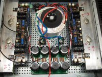
All finished except the shouting...
I couldn't have finished this without help from Zen Mod and Dennis Hui. Thank you. And thanks to Nelson Pass for the design.
The proof is in the pudding and tomorrow it will get installed into my system.
Attached are a couple photos and the printout of QA401 output. Looks like about 11 or 12 watts is the useable output. I was surprised at the amount of 3rd harmonics.
This is cased in a 3U by 400mm case and hardly even gets warm. I could have used a 2U by 400 dissipante and been fine. I guess the big factor is the single die VFETs instead of the normal ones. The 'T' brackets were no longer available so I had to make my own. Probably overkill also.
Attachments

Last edited:
Hi hirscwi,
Nice work, I always enjoy seeing an amplifier with all its wires twisted.
The distortion is H3 dominant because the amplifier is push-pull, as the even order harmonics tend to cancel each other. But that shouldn't prevent you from enjoying the sound.🙂
Nice work, I always enjoy seeing an amplifier with all its wires twisted.
The distortion is H3 dominant because the amplifier is push-pull, as the even order harmonics tend to cancel each other. But that shouldn't prevent you from enjoying the sound.🙂
I've had some listening time with this amp. UGS preamp and Tekton Design Lore S speakers. It sounds really nice (I guess that's no surprise).
It's cased in a 3U 400mmD dissipante case and it doesn't even feel warm to the touch. I wonder if I should bump up the bias? I am using the baby VFETs (k60/J18) and biased at half the normal amount.
Probably I should just not worry about it. Maybe put it into a smaller case at some point (seems like a lot of effort, tho).
Cheers and thanks for the help to get me to this point. Now I just need to finish my Stasis 2020...
Last edited:
Gentlemen,
I am using bipolar bench supply at 28v.
While applying power to the front end, I observed the following test results:
G-T6,T8..13.8V instead of +28v
G-T4,T2..-13.8V instead of -28v
G-T14,15...5.9V istead of +-13v
All other measurements are within specs.
Need your help to find out what did i did wrong.
Any suggestion how to proceed is welcome
Thanks
Roumen
Last edited:


I'm guessing you only have +/-14VDC there. Please check by just measuring
the DC voltage between the + and - terminals.
the DC voltage between the + and - terminals.
The kit arrived with fqp3n30/3qp3p20 mosfets for Q5/Q6.
Do i have to change p3 and p4 to 1k.....and r34 and r35 to 500 ohms
Thank you
Roumen
Do i have to change p3 and p4 to 1k.....and r34 and r35 to 500 ohms
Thank you
Roumen
- Home
- Amplifiers
- Pass Labs
- Sony vFET Illustrated build guide