Rodeodave, beautiful build. I finished my Part 2 build with the same "AL" PCBs a couple months ago, and know exactly what drilling the L bracket entails. Measure, remeasure, drill, deburr, clean, repeat. It took me a while. Four DMMs made it convenient to adjust each channel. Otherwise it is a straightforward build. Let us know when you are done so we can compare notes on its sound.
Very nice Dave! It's great to see another one being built.
Do you plan to run at the standard 1A or a bit higher?
Do you plan to run at the standard 1A or a bit higher?
Thanks guys, your comments mean a lot to me 
I'm really looking forward to comparing the amp's sound with and without global negative feedback. Being able to switch it in and out with a jumper bridge is a pretty cool feature.
Tweaking the bias current will largely depend on how well the heatsinking works with the mounting bracket (6mm extruded aluminum profile), grease junction and finned radiators. By my estimates, the targeted 1A should be plenty fine, with some leeway in increasing the bias.
Speaking of heatsinks, I made some progress:
Goop

Torque

Squeeze

If you take a closer look at the screws, you'll notice that I started with torquing down the two in the middle at the bottom. The idea was to squeeze the goop upwards and outwards, starting from the middle at the bottom. I then torqued down the two outermost screws in the bottom row, diving the goop further upwards. After half an hour or letting it creep, I torqued down the upper row of screws, again starting from the middle. Virtually all the excess goop squoze out up top, as planned.
And after cleaning up the excess goop we get this:

If things go as planned, I'll be firing them up on the bench tonight. Stay tuned!
I'm really looking forward to comparing the amp's sound with and without global negative feedback. Being able to switch it in and out with a jumper bridge is a pretty cool feature.
Tweaking the bias current will largely depend on how well the heatsinking works with the mounting bracket (6mm extruded aluminum profile), grease junction and finned radiators. By my estimates, the targeted 1A should be plenty fine, with some leeway in increasing the bias.
Speaking of heatsinks, I made some progress:
Goop
Torque
Squeeze
If you take a closer look at the screws, you'll notice that I started with torquing down the two in the middle at the bottom. The idea was to squeeze the goop upwards and outwards, starting from the middle at the bottom. I then torqued down the two outermost screws in the bottom row, diving the goop further upwards. After half an hour or letting it creep, I torqued down the upper row of screws, again starting from the middle. Virtually all the excess goop squoze out up top, as planned.
And after cleaning up the excess goop we get this:
If things go as planned, I'll be firing them up on the bench tonight. Stay tuned!
Alright, I managed to fire up each channel with a bench top PSU putting out a regulated +/-28V. Everything went smoothly, and all voltages are right on spec. I set the bias current to 1A for now, once the amp enclosure is put together we'll see how far it can be pushed.

Next up is the PSU, mains wiring and input/output wiring. It'll be a while until the next update...
Next up is the PSU, mains wiring and input/output wiring. It'll be a while until the next update...


Lol, no, it's a stress relief ball for when things don't go as planned. Very therapeutic.
Other than that, meters, batteries, amps, can't have too many, I fully agree.
Other than that, meters, batteries, amps, can't have too many, I fully agree.
Hello,
I am looking to buy 2 circuit boards Vfett Csx1 created by Permander at the time who unfortunately died.
To make me a second amp like this. 😉
I remember that Walterw, Soundhappy, Zen Mod, Variac had done this project.
If anyone can put me in touch with someone.
I am looking to buy 2 circuit boards Vfett Csx1 created by Permander at the time who unfortunately died.
To make me a second amp like this. 😉
I remember that Walterw, Soundhappy, Zen Mod, Variac had done this project.
If anyone can put me in touch with someone.
I have boards intended for use, but after chatting with Super_BQ I am a little unsure as he experienced hum problems. Input transformer too close to mains transformer. I should maybe do a better PCB. But decided to give the PCBS a try.
Well, report soon. Hopefully.
Well, report soon. Hopefully.
I have a pair I. Email me 😉Hello,
I am looking to buy 2 circuit boards Vfett Csx1 created by Permander at the time who unfortunately died.
To make me a second amp like this. 😉
I remember that Walterw, Soundhappy, Zen Mod, Variac had done this project.
If anyone can put me in touch with someone.
Hi All. This is my build, just to remind:
Well, I was trying to configure as a fully balanced monoblock, however was only able to get 13,5V RMS of 1kHz swing until clipping, which only gives 22 watts @4 ohm, respectively. Now I want to try it in parallel to get more power. Just with single FE and two OS parallelled. Couple of questions here:
1. Shall I make some feedback just for OS (output to junction of R41-R42), say, with inverting opamp, just to ensure them both are quite precise with dc offset?
2. Overall NFB R23-R46 shall be as is?
Thanks for your thoughts.
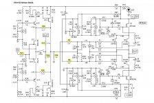
Hi everyone, I've managed to get myself one of these amps and I'm (hopefully) starting to understand it's workings.
I'm thinking of changing the 4-off 47uF caps for 100uF items, with an increase in the larger 220uF caps to 1500uF Pana FM's.
As long as the ratio of >4.6 between C3 and C1 is maintained then I believe that all will be well.
Is this correct?
Many thanks
I'm thinking of changing the 4-off 47uF caps for 100uF items, with an increase in the larger 220uF caps to 1500uF Pana FM's.
As long as the ratio of >4.6 between C3 and C1 is maintained then I believe that all will be well.
Is this correct?
Many thanks
Dan, it would be smarter to up the Voltage and not the uF. You can damage the unit by going up that much in value.
Anyway, I upped the voltage on most of the power caps and put a bypass on the filter caps.
Anyway, I upped the voltage on most of the power caps and put a bypass on the filter caps.
I've rebuilt it to get the required +/-28V at the rails. The amp in question has been built with Silmic 2's, which I'm not a fan of. My thinking was to replace all the 47uF it's with 16V 100uF Audio Note caps and the larger ones with something 460uF+. The 1500uF 35V Pana FM seemed a good candidate
- Home
- Amplifiers
- Pass Labs
- Sony vFET Amplifier Part 2