Has anyone varied the bias on their Sony VFETs and posted the distortion plots?
There must have been a ton of research done on this over the years.
There must have been a ton of research done on this over the years.
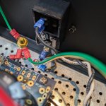
I have a question regarding the gate resistors to the VFETs on the R0 amp
Why are they needed?
These are R25 & R26, plenty of power amps don't use a base/ gate resistor at all. Why here and why 221R?
Same question applies to the M2, but in that case they are 100R.
I know some amps use a diode from gate to source as start-up/ shut-down protection, but given the delay provided by C3 vs C1, is that necessary / worth adding?
Thanks for the help 🙂
Last edited:
all parts are having interelectrode capacitances
those are so called "gate stoppers", to tame unwanted HF oscillations
or, if you're of Kosher Aficionados, you can omit them and find adequate Ferrite beads to install in gate leads
same purpose, zero Rdc, looking fancy, you can bash they're made of Preputium

those are so called "gate stoppers", to tame unwanted HF oscillations
or, if you're of Kosher Aficionados, you can omit them and find adequate Ferrite beads to install in gate leads
same purpose, zero Rdc, looking fancy, you can bash they're made of Preputium

ZM, I knew you were just the man to answer this one 🙂
For triodes I know that with careful design grid stoppers can be removed (use a diode for shut down, delayed HV at start, short leads, correct value of PSU bleed resistors. etc).
The JLH Le Monstre doesn't use them. No Bedini amps used them. Concordant pre amps dont either.
I did see that you like a protective diode and 100R for the LuDEF and the SissySIT.
I would maybe want to delete the resistors and replace with a ferrite, possibly with an additional diode. Possibly with just a wire...
More research needed on my side
Last edited:
today I almost know how little I know;
yesterday, when I wasn't even aware of fact how squat I know, I was obsessing about everything, including parts which are welcome and necessary
heck, removing foils from elco caps, and anything else I could think of ........ luckily never got to stage of removing fuses from necessary positions
anyhow, invest some energy in actually learning what's role of specific positions in circuits of interest, then analyze what's benefit of having them and what's benefit of excluding them
this is internet; learn first to doubt anything you read here ( well, certainly including my ramblings)
everyone is having a keyboard; everyone is having link to internet; everyone is having an opinion; everyone is prone to Preaching; give it time - everyone starts Preaching; Dr. Haus - "everybody lies"
make a research your main goal, to ook with amps - you have one, you already have them all**
knowledge is important, amps are not
**if you didn't learn anything with that one, wtf you need another one?
I've seen triode circuits oscillate on account of grid stop resistors; I think you'll find that the circuit can actually be a bit quieter when they are present.ZM, I knew you were just the man to answer this one 🙂
For triodes I know that with careful design grid stoppers can be removed (use a diode for shut down, delayed HV at start, short leads, correct value of PSU bleed resistors. etc).
In the case of gate stop resistors, an oscillation can damage output devices pretty quickly as well as tweeters. The grid and gate stop resistors can be used to take advantage of Miller Effect in the active device so you can use them to limit bandwidth to help reject unwanted RF. You can use a simple formula to calculate the -3dB pont in a tube circuit. In a solid state circuit the input capacitance can be non-linear so the use of stopping resistors becomes more important.
The oscillation can start due to a reflection of the signal once it hits the grid/gate of the device. With nothing to 'stop' it, the bounced signal can find a resonance or thru superposition go into excitation. RF beads would have to be carefully chosen for best effect. Its much easier to use a resistor.
After a long time first collecting parts and then building with no rush, I finished this amp - finally. It sounds absolutely wonderful.
So, thanks a million to Papa for an exiting project and an easy to understand adjustment procedure, and to 6L6 for a great build guide with all the comments. Thank you.
I re-adjusted the front end after the Vfets were installed (with enough multi-meters and patience) as I was not happy with the T18 voltage. In one channel it was around 2 volts, with the feedback loop operating. These are my numbers now:
I have one question: The R32 voltage drop (bias current) is rock stable, when the amp is hot. At power on it shortly raises to around 130mV for a couple of seconds, but it drops rapidly as the bias circuit wakes fully up. After less than a minute it is below 105mV. As the amp heats up it steadily settles in at 100mV, but it takes 15-20 minutes. Is this too long running at the slightly elevated current 100-105mV - so I should bias lower, or is there enough margin with the VFETs?
So, thanks a million to Papa for an exiting project and an easy to understand adjustment procedure, and to 6L6 for a great build guide with all the comments. Thank you.
I re-adjusted the front end after the Vfets were installed (with enough multi-meters and patience) as I was not happy with the T18 voltage. In one channel it was around 2 volts, with the feedback loop operating. These are my numbers now:
Test point | Voltage Left channel | Voltage Right channel | |
T1 to -28V | 101mV | 100mV | |
T2 | 24.0 | 23.8 | |
T4 | -23.9 | -23.9 | |
T3 | 19.5 | 19.3 | |
T5 | -19.4 | -19.4 | |
T6-T7 | 1.47 | 1.50 | |
T9-T8 | 1.47 | 1.51 | |
T7 | 25.9 | 25.9 | |
T9 | -25.7 | -25.7 | |
T10 | 21.1 | 21.1 | |
T12 | -21.1 | -21.2 | |
T18 | -5 to 50mV | 90 to 150mV | |
T14 | 12.8 | 13.1 | |
T15 | -12.7 | -13.0 | |
T16 | 9.6 | 9.6 | VGS 10.5 |
T17 | -8.5 | -8.4 | VGS 9.4 |
Output offset | <10mV | <15mV | |
I have one question: The R32 voltage drop (bias current) is rock stable, when the amp is hot. At power on it shortly raises to around 130mV for a couple of seconds, but it drops rapidly as the bias circuit wakes fully up. After less than a minute it is below 105mV. As the amp heats up it steadily settles in at 100mV, but it takes 15-20 minutes. Is this too long running at the slightly elevated current 100-105mV - so I should bias lower, or is there enough margin with the VFETs?
No worry there at all. Just as a matter of comparison, the same parts in the single-ended Sony vfet amps run at similar Vds voltages but at 1.6A.
Enjoy your amp.
Enjoy your amp.
LOL. Very kind of you. Okay, I will pop the hood and take and post a few shots when I am back home in a couple days.
Cheers
Cheers
Thanks. I think this is my best power amp yet (counting 2 commercial and 2 DIY). Cool that you did the brackets yourself PierreQuiRoule, please share more pictures when you have time 🙂. I took the easy Modushop solution with finished brackets.
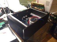
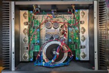
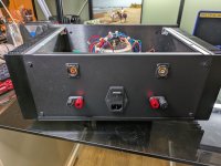
Mine is build with C-R-L-C power supply, the extra R is to improve the impulse response to disturbances. The front plate is inspired by the single ended diyaudio VFET chassis. Here are a few pictures:


PS: The logo says "PASS diy" for tribute - and not for spiking emotional discussions. Should I redo it, the PASS and diy should overlap in the logo.
Mine is build with C-R-L-C power supply, the extra R is to improve the impulse response to disturbances. The front plate is inspired by the single ended diyaudio VFET chassis. Here are a few pictures:
PS: The logo says "PASS diy" for tribute - and not for spiking emotional discussions. Should I redo it, the PASS and diy should overlap in the logo.
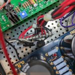
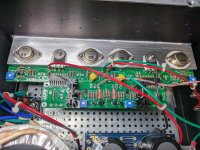
The construction of the Push-Pull VFET amp is straightforward but took me a while. Working with irreplaceable VFETs incites slow, cautious assembly and testing. I followed the original design published by Mr. Pass in 2015, using four VFETs per channel, delivering 20 watts into 8 ohms and 40 watts into 4 ohms. PCBs are from a 2018 group buy "GB Pass SONY VFET Version 2 - AL Boards" by @Tea-Bag.
Aspiring builders should note that Mr. Pass revised some resistor values after the original article. In his post on 2015-08-11 9:49 pm he writes:
“R5 = 10K
R6 = 10K
R20 = 10K
R21 = 2.21K
R23 = 4.75K
R24 = 332
R29 = 22.1K
R30 = 22.1K
R46 = OPEN
SW = closed.
These values support less work by the input transistors. R24 can be adjusted for more or less gain within a reasonable range.”
The schematic appeared also in a Japanese magazine with minor differences. The amplifier was judged by Mr Pass and team to sound better with feedback, so this is how I built and listen to mine.
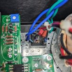
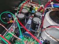
Readers will recognize the Modushop 4U Deluxe chassis with steel covers. The chassis was tight and I chose to stack two smaller 22VAC Antek transformers to trade width for height. One transformer generates the positive supply, the other the negative one, and each channel gets its dedicated CRC filtering board. If I were to do it again I would use a single transformer to reduce wiring. Drilling holes in the L brackets took a while.
Tip: Transparent silicone tubing can be cut to desired length to make insulators for TO-3 pins and mounting bolts. Size 4mm x 6 mm (internal diameter x outer diameter) is readily available online, cheap, and fits perfectly.
As recommended, I adjusted bias and DC offset after warmup. To be on the safe side, I set bias current to 1A which worked fine in a 4U size chassis.
This amplifier reminds me of my slightly warmer-sounding DIY F4; however with gain of course and perhaps even a bit more tonal neutrality and microresolution - which was unexpected. I would not describe this amp as cold or bright. Just very neutral. My favorite preamp pairing with this amp is John Broskie's Aikido, an my favorite tube in this Aikido is the NOS US-made Raytheon 6CG7.
Aspiring builders should note that Mr. Pass revised some resistor values after the original article. In his post on 2015-08-11 9:49 pm he writes:
“R5 = 10K
R6 = 10K
R20 = 10K
R21 = 2.21K
R23 = 4.75K
R24 = 332
R29 = 22.1K
R30 = 22.1K
R46 = OPEN
SW = closed.
These values support less work by the input transistors. R24 can be adjusted for more or less gain within a reasonable range.”
The schematic appeared also in a Japanese magazine with minor differences. The amplifier was judged by Mr Pass and team to sound better with feedback, so this is how I built and listen to mine.
Readers will recognize the Modushop 4U Deluxe chassis with steel covers. The chassis was tight and I chose to stack two smaller 22VAC Antek transformers to trade width for height. One transformer generates the positive supply, the other the negative one, and each channel gets its dedicated CRC filtering board. If I were to do it again I would use a single transformer to reduce wiring. Drilling holes in the L brackets took a while.
Tip: Transparent silicone tubing can be cut to desired length to make insulators for TO-3 pins and mounting bolts. Size 4mm x 6 mm (internal diameter x outer diameter) is readily available online, cheap, and fits perfectly.
As recommended, I adjusted bias and DC offset after warmup. To be on the safe side, I set bias current to 1A which worked fine in a 4U size chassis.
This amplifier reminds me of my slightly warmer-sounding DIY F4; however with gain of course and perhaps even a bit more tonal neutrality and microresolution - which was unexpected. I would not describe this amp as cold or bright. Just very neutral. My favorite preamp pairing with this amp is John Broskie's Aikido, an my favorite tube in this Aikido is the NOS US-made Raytheon 6CG7.
Attachments
-
 PXL_20231228_161608199.jpg525.8 KB · Views: 178
 -
 PXL_20231228_161539274.jpg668.5 KB · Views: 188
 -
 PXL_20231228_161657618.jpg620.3 KB · Views: 182
 -
 PXL_20231228_161638767.jpg623.3 KB · Views: 165
 -
 PXL_20231228_161809626.jpg599.2 KB · Views: 154
 -
 PXL_20231228_161914978.jpg439.9 KB · Views: 153
 -
 PXL_20231228_161741751.jpg539.4 KB · Views: 151
Thank you Dennis.
By the way, after a year of daily use, the DC offset is still below 20 mV after warm up. This is a lovely and very stable amp.

By the way, after a year of daily use, the DC offset is still below 20 mV after warm up. This is a lovely and very stable amp.
Last edited:
- Home
- Amplifiers
- Pass Labs
- Sony vFET Amplifier Part 2