Maybe this pair of fully built Sony PP boards is interesting for you guys:
https://www.diyaudio.com/community/...-boards-curve-matched-vfets-available.407200/
https://www.diyaudio.com/community/...-boards-curve-matched-vfets-available.407200/
Thanks. Just wanted to make sure, the weirdest things are being faked these days and at least where I live they only seem to be available from small vendors at a relatively high price.
Last edited:
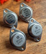
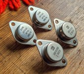
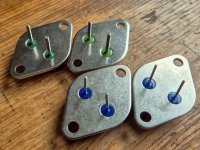
It's good to be cautious and test them before use. Heck, recently a member bought fake ZTX450/ZTX550 and they're in production and easily available...the weirdest things are being faked these days
only because of the thread and "someone's" got to say it: real or not, they are not vfetsAny views on whether these are genuine parts?
Thanks
Sven

Ha! Maybe I should start collecting IRF pucks and do a group buy for Sony VFETs + IRF puck combos 🙂
It's perfectly fine to use the TO-247 versions (IRFP240/IRFP9240) though some might prefer the look of the TO-3 parts.Thanks, I know that. Still needed for the amplifier discussed in this thread though. 🙂
I have had 7 Sony Vfet amps and none of them looked like that. A "tech" used a variac on one (blew all of them up) and I bought some "Vfet's" on Ebay to replace them and they were fake Chinese.... some sellers have no shame!
I understood that Abraxas is asking for these, having on mind Papa's Sony VFet amp having exactly these mosfets as rails conditioners
I'm sure that I understood correctly

I'm sure that I understood correctly
Hi All.
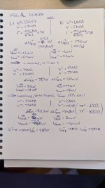
Just another build of Rev-2 with Teabag boards. However, now used 3 pairs of k82/j28 per channel and the Front End is powered by separate regulated PSU +/-33V from separate trafo. Also adjusted rails from +/-19 to +/-24, to be a bit closer to 40-th anniversary commemorative thing. The amp is giving 15.2V RMS before clipping at 4ohms dummy load, so it is about 58 WPC. Bandwith is narrow than original, going to moderate decline from 40kHz. Biased at 1 amp per channel.
Just another build of Rev-2 with Teabag boards. However, now used 3 pairs of k82/j28 per channel and the Front End is powered by separate regulated PSU +/-33V from separate trafo. Also adjusted rails from +/-19 to +/-24, to be a bit closer to 40-th anniversary commemorative thing. The amp is giving 15.2V RMS before clipping at 4ohms dummy load, so it is about 58 WPC. Bandwith is narrow than original, going to moderate decline from 40kHz. Biased at 1 amp per channel.
Attachments

Last edited:
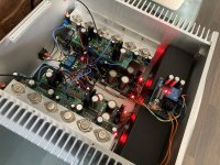
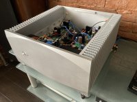
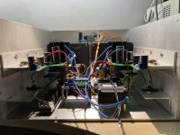
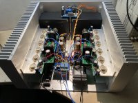
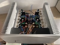
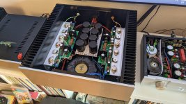
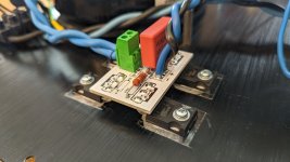
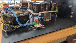
Alright, another Sony VFET Amplifier Part 2 (a.k.a. VFET AL) has come alive!
After getting the boards up and running as pictured in https://www.diyaudio.com/community/threads/sony-vfet-amplifier-part-2.276711/page-211#post-6920565 the project got once again put on the back burner for quite a while. But now that fall/winter is coming, it’s time for bringing out the space heaters.
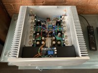
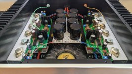
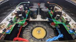
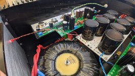
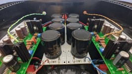
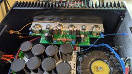
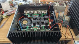
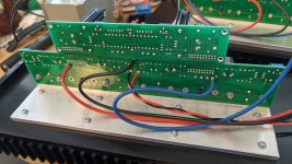
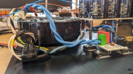
The PSU is a classic CCRCC with 4x33mF 35V caps and a 0R15 1% 10W WW resistor per polarity. 600VA 2x22VAC toroidy transformer, 60A 300V Hyperfast 60APH03 rectifiers and Quasimodo-derived 0u22/10R snubbers. Hiding underneath the PSU pcb, we’ve got a beefy EPCOS 250V 22A line filter. And believe it or not, a lowly CL-60 thermistor is taking good care of the inrush current. No fuse tripping so far. With a meager 7W test load (120R), The PSU puts out +29.28V/-29.27V DC.

The completed amp came alive without a hitch, each channel drawing pretty much exactly 1A per polarity, just as previously set. The bias was measured over 0R1 resistors that had been temporarily put in circuit. After warming up and the tiniest bit of fiddling with the frontend bias, the PSU is settling at +/- 27.5V, with a steady current draw of 2A per polarity (about 324mV over the 0R15 PSU resistors). Each channel’s output offset settles at about -20mV. The heatsinks (150mm height, 412mm length) are, using established nomenclature, just about blimey hot (I’m guessing 45°C).

Deviating from the objective observations, a few words on the amp’s sound. My previous amp is/was the single-output-pair diy Sony VFET from 2017 (see post 2673 at https://www.diyaudio.com/community/threads/sony-vfet-amplifier-part-2.276711/page-134#post-4980105 for example). Source is a DCB1 buffered dam1021 and a BA-3 preamp. Clearly there’s a familiarity in the sound, but I dare say that the VFET AL is simply more better. More texture, more sparkle, more oomph. While I haven’t heard a full fledged F4 yet (just a single output pair F4 as seen in post 2039 at https://www.diyaudio.com/community/...ass-f4-amplifier.234355/page-102#post-6281443), listening to the AL reminded me of listening to the F4 for the first time. So much detail, so much space. This one’s going to be hard to beat.


I’ll keep listening for a couple of days now before pulling some more numbers from the circuit. Until then!
After getting the boards up and running as pictured in https://www.diyaudio.com/community/threads/sony-vfet-amplifier-part-2.276711/page-211#post-6920565 the project got once again put on the back burner for quite a while. But now that fall/winter is coming, it’s time for bringing out the space heaters.
The PSU is a classic CCRCC with 4x33mF 35V caps and a 0R15 1% 10W WW resistor per polarity. 600VA 2x22VAC toroidy transformer, 60A 300V Hyperfast 60APH03 rectifiers and Quasimodo-derived 0u22/10R snubbers. Hiding underneath the PSU pcb, we’ve got a beefy EPCOS 250V 22A line filter. And believe it or not, a lowly CL-60 thermistor is taking good care of the inrush current. No fuse tripping so far. With a meager 7W test load (120R), The PSU puts out +29.28V/-29.27V DC.
The completed amp came alive without a hitch, each channel drawing pretty much exactly 1A per polarity, just as previously set. The bias was measured over 0R1 resistors that had been temporarily put in circuit. After warming up and the tiniest bit of fiddling with the frontend bias, the PSU is settling at +/- 27.5V, with a steady current draw of 2A per polarity (about 324mV over the 0R15 PSU resistors). Each channel’s output offset settles at about -20mV. The heatsinks (150mm height, 412mm length) are, using established nomenclature, just about blimey hot (I’m guessing 45°C).
Deviating from the objective observations, a few words on the amp’s sound. My previous amp is/was the single-output-pair diy Sony VFET from 2017 (see post 2673 at https://www.diyaudio.com/community/threads/sony-vfet-amplifier-part-2.276711/page-134#post-4980105 for example). Source is a DCB1 buffered dam1021 and a BA-3 preamp. Clearly there’s a familiarity in the sound, but I dare say that the VFET AL is simply more better. More texture, more sparkle, more oomph. While I haven’t heard a full fledged F4 yet (just a single output pair F4 as seen in post 2039 at https://www.diyaudio.com/community/...ass-f4-amplifier.234355/page-102#post-6281443), listening to the AL reminded me of listening to the F4 for the first time. So much detail, so much space. This one’s going to be hard to beat.
I’ll keep listening for a couple of days now before pulling some more numbers from the circuit. Until then!
Attachments
-
 PXL_20240929_075949403.jpg387.8 KB · Views: 137
 -
 PXL_20240929_080020520.jpg416.1 KB · Views: 114
 -
 PXL_20240929_080048002.jpg434.5 KB · Views: 114
 -
 PXL_20240929_080053842.jpg384.2 KB · Views: 116
 -
 PXL_20240929_162605287.jpg459.9 KB · Views: 124
 -
 PXL_20240929_162616227.jpg430.7 KB · Views: 135
 -
 PXL_20240929_080118491.jpg251 KB · Views: 144
 -
 PXL_20240928_130135800.jpg524.4 KB · Views: 132
 -
 PXL_20240928_090817108.jpg375.5 KB · Views: 111
 -
 PXL_20240928_080643917.jpg365.1 KB · Views: 112
 -
 PXL_20240928_080610467.jpg316.8 KB · Views: 111
 -
 PXL_20240928_080533608.jpg375 KB · Views: 111
 -
 PXL_20240928_080439585.jpg437 KB · Views: 128
@Rodeodave : Wonderful build! It's always great to see another VFET AL.
I see a Rubik's cube you can work on now that the amp is done. 🙂

I see a Rubik's cube you can work on now that the amp is done. 🙂
Pass DIY Addict
Joined 2000
Paid Member
- Home
- Amplifiers
- Pass Labs
- Sony vFET Amplifier Part 2