Okay, here is a taste of a possible board(s) to work with here. Critism welcome.
I am hoping that Nelson doesn't throw the baby out with the bathwater and re-invent the thing on the next rendition, but if so, I'll move on.
The pcb in the article was 14" x 2.75", shown here. My intention was to
drop the zeners, use TO-247's for the Mosfets, set it up for single pairs also
and maybe make it a little smaller.
Attachments

this time I had no good luck…… :-(
I bought at Taobao two pairs of SK82/SJ28, 200 Yuan the pair.
The vendor even lifted the price from 200 to 300 Yuan/pair.
😡😡😡
But your sacrifice to diyaudio does not go unseen. Your noble sarifice has probably saved some others from wasting there time.

Thanks for showing us the real deal.The pcb in the article was 14" x 2.75", shown here. My intention was to
drop the zeners, use TO-247's for the Mosfets, set it up for single pairs also
and maybe make it a little smaller.
Hmmm. I thought the Zeners in the output stage where there for assisting in voltage setting, but that is NOT what the article says. If they are removed, can we just jumper them?😕
Edit: I guess I see the diodes facing each other, that is a clue to their nature 🙂
Last edited:
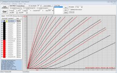
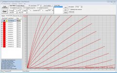
Hello generg. I hope that you are well. Do the plots for the Taobao devices mean that they are still VFETs which are out-of specifications; meaning that they were rejects for use in SONY or Yamaha hi-fi amps?this time I had no good luck…… :-(
I bought at Taobao two pairs of SK82/SJ28, 200 Yuan the pair.
https://item.taobao.com/item.htm?spm=a230r.1.14.140.l4ezPb&id=40300679359&ns=1&abbucket=18
look at the four flat curves, these are the new ones,
the four steeper curves are two pairs from Acronman I already had……
The vendor even lifted the price from 200 to 300 Yuan/pair.
😡😡😡
the zeners protect the Sonys, omit them simply and do not jumper them….
Am I right?
🙂
"Similarly there are Zener Diodes sprinkled around to protect the Gates of the
power transistors from damage. Half-Watt Zeners at the nominal voltages called
out will be just fine. I have run the amplifiers extensively without any of these
diodes without problems, but I would not expect all amplifier users to observe
the ordinary precautions. You can use your own judgment on this."
Last edited:
Hello generg. I hope that you are well. Do the plots for the Taobao devices mean that they are still VFETs which are out-of specifications; meaning that they were rejects for use in SONY or Yamaha hi-fi amps?
Walter asked the same…. 🙂
after some tea and disappointment swallowed away I will look for this…
I suppose they are the ones with less transconductance
2SK60/2SJ18, with one die only…
https://item.taobao.com/item.htm?spm=a1z10.1-c.w4004-11665682645.19.UsLhPq&id=40300123246
offered from the same vendor…..
The pcb in the article was 14" x 2.75", shown here. My intention was to
drop the zeners, use TO-247's for the Mosfets, set it up for single pairs also
and maybe make it a little smaller.
@ Mr Pass
Pcb for two Vfet matched pairs with to-3 Irf's are my must build.
I have wait 2 years for this diy project and prepared batch of dozen pairs and i know similar diyers.
FW boards style have always elegant logic clear layout.
Large distance between power transistors and longer L profile that really cool for thermal disipation.
Conclusion could two versions be made for DiyAudio Store kit's
one for original amplifier topology from article Vfet Part 2 say " De Luxe "
and another simplified and little smaller ?
Yes please let's drop zeners.
Kind regards 🙂
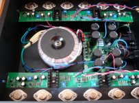
o.k. more stuff concerning Taobao offer!
the good news: they are SITs!
the bad news: these JE types do not fit in any way to my Acronman stuff, so if you want to complete your Acronman SITs with these from Taobao the chance to get fitting parts to have more pairs could be very low.
When you order only from Taobao, let us say 10-20 it might give pairs as well.
Left picture: two SK82 JE from Taobao source
right picture: one SJ28 JE from Taobao source
Attachments
Thanks for showing us the real deal.
…..
Thank you for your work Mike! Clever as always!
Not everybody has First Watt cases…… 🙂
Thank you for your work Mike! Clever as always!
Not everybody has First Watt cases…… 🙂
Papa pcb are 14 " = 35.56 centimeters
Good news 4U or 5U chassis internal are 36.00 cm
it's perfect equal heat distribution for vfet's and irf´s
🙂
🙂Attachments
I am unhappy that teabag and CRT work for a PCP certainly some time, they present it, give it free for discussion.......And now......
First time I feel something like PassMania.....
Maybe I am not objective, just a feeling....
:-(
First time I feel something like PassMania.....
Maybe I am not objective, just a feeling....
:-(
Okay, here is a taste of a possible board(s) to work with here. Critism welcome.
I am hoping that Nelson doesn't throw the baby out with the bathwater and re-invent the thing on the next rendition, but if so, I'll move on.

Here is what it will look like kind of mounted. Similiar to Permanders board, with a more modular front end.

edit: added attachment so one can see it bigger and better.
Love your idea and layout Tea-bag but have a small concern of the input module heatsinks on top of the MB tracks.
What about making input module plugin and changing heatsink type so it does not hit the PCB tracks?
I like flexibility what can i tell you 😀😀😀
Last edited:
I am unhappy that teabag and CRT work for a PCP certainly some time, they present it, give it free for discussion.......And now......
First time I feel something like PassMania.....
Maybe I am not objective, just a feeling....
:-(
I feel the same, but Teabag has always given us different PCBs for different layouts.... so there is more to choose...

I like people with feelings but gentlemen like you my dear friends.
---what can i tell you neighbor....papa's pcb is perfect and tested in papa box....but DIYers love to push the limits.....after all that is where the fun is 😀😀😀😀😀
- Home
- Amplifiers
- Pass Labs
- Sony vFET Amplifier Part 2