Love your idea and layout Tea-bag but have a small concern of the input module heatsinks on top of the MB tracks.
What about making input module plugin and changing heatsink type so it does not hit the PCB tracks?
I like flexibility what can i tell you 😀😀😀
My original idea was for a daugter card for the Fe board, an angle one may still be possible but it's got to hold a fair amount of weight with heatsinks.
I also dont think, since Papa uses heatsinks directly on his board, that the ones in use would draw get very warm. For me, I would probably dable a chunk of rope caulk on the board where the heatsinks may lay.
It certainly is a debatable idea. There was interested presented to me for some to just use the front end as pre-amplifer and wished for a seperate board, and Nelson also discussed optional output for mosfets. So I try to make things removable and re-purposed if possible. (I think it needs some mounting holes here too)
Some additions to the front end board are source resistors for JFETs and use of TO-220 or TO-92 type bipolars.
If people wish to hold out for a Nelson created board layout, I won't lose any sleep. I am just trying to provide an option. With the scarcity of resources, I don't imagine a lot of boards being built for this design unfortunately, so it's really a more rare science project for those of us who cannot possibly help ourselves.

...
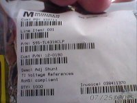
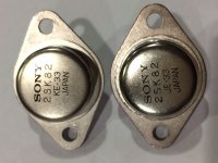
the good news: they are SITs!
the bad news: these JE types do not fit in any way to my Acronman stuff, so if you want to complete your Acronman SITs with these from Taobao the chance to get fitting parts to have more pairs could be very low.
...
...
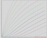
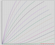
Something I can tell from the dozens that I measured:
...
- They do display the triode curves of VFETs, I tend to believe they're genuine Sony VFETs.
- As far as I can tell, the JAs are more linear than the KEs and KFs, but they have lower transconductance at the same time.
- With the lower transconductance, I suspected they might be re-badged 2SK60/SJ18. So I drilled open the bad one, but the chip inside seems to be a 4mm chip, so they're not 2SK60/SJ18 which have 3mm chip.
Hi generg,
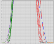
Your observation are same as mine before. They're certainly SITs, and quite linear actually (first 2 curves as samples), but the JAs have lower transconductance (flatter slope, red and green from last pic are KE/KFs from acronman, blue and purple are JAs).
This characteristic is very consistent for the samples I've measured, to the extent I doubt they are re-badged SITs of other model. But VFETs in Sony style casing with dual chip - I can't think of any explanation, except that early 2SK82/SJ28s (JAs are much earlier than KFs, by the alphabetical order) may have a characteristics somewhat different from latter ones.
Attachments
You understand that I am not interested if people want to use my board or
not. The DIYAudio store has asked to be able to have a pc board available,
and if Tea-Bag would like them to use his, it's that much less work for me.
If he is like me, he is used to revising artwork...
BTW, I think there is a preference for the TO-247 on the regulators.
Also, I think a switching supply version could be made that eliminates most if
not all the regulators, and might make this more buildable for DIYers.
Ooooooohhhh. Look what just arrived.
Attachments
The DIYAudio store has asked to be able to have a pc board available....
If DiyAudio Team open new thread about potential interest for estimate quantity Vfet Part 2
pcb's versions or kit's versions we can see all aficionados needs and this can help
to go preparation and production step 🙂
Bob Ross " happy little threes " fews 12 it's plenty for this amp 😀Ooooooohhhh. Look what just arrived.
Best regards
Attachments
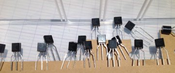
Yes, a lot of little 3 legged critters in this design. I am trying not to be too intimidated. 😱
per Tea Bag
"If people wish to hold out for a Nelson created board layout, I won't lose any sleep. I am just trying to provide an option. With the scarcity of resources, I don't imagine a lot of boards being built for this design unfortunately, so it's really a more rare science project for those of us who cannot possibly help ourselves."
per Nelson
" I think a switching supply version could be made that eliminates most if
not all the regulators, and might make this more buildable for DIYers".
I, for one, love both rare science projects and simplicity/buildability. I could see building both board sets using only single pairs. I've said a VFET is the last amp I am going to build so I should/must pursue all options including maybe even bridging for completeness. 😀😀😀
Hi generg,
Your observation are same as mine before. They're certainly SITs, and quite linear actually (first 2 curves as samples), but the JAs have lower transconductance (flatter slope, red and green from last pic are KE/KFs from acronman, blue and purple are JAs).
This characteristic is very consistent for the samples I've measured, to the extent I doubt they are re-badged SITs of other model. But VFETs in Sony style casing with dual chip - I can't think of any explanation, except that early 2SK82/SJ28s (JAs are much earlier than KFs, by the alphabetical order) may have a characteristics somewhat different from latter ones.
Hi cwtim,
thanks for your understanding that I made possibly some irritation with my first posting concerning the JAs…..
I was so disappointed that I could not use them to make more pairs with my Acronman devices that I first thought that they might be fakes….
They are not and you explained possible reasons, thank you!
🙂
per Tea Bag
"If people wish to hold out for a Nelson created board layout, I won't lose any sleep. I am just trying to provide an option. With the scarcity of resources, I don't imagine a lot of boards being built for this design unfortunately, so it's really a more rare science project for those of us who cannot possibly help ourselves."
I, for one, love both rare science projects and simplicity/buildability. I could see building both board sets using only single pairs. I've said a VFET is the last amp I am going to build so I should/must pursue all options including maybe even bridging for completeness. 😀😀😀
Okay, you unknowingly just volunteered as a proto-builder for the board.:😱
Hi cwtim,
thanks for your understanding that I made possibly some irritation with my first posting concerning the JAs…..
I was so disappointed that I could not use them to make more pairs with my Acronman devices that I first thought that they might be fakes….
They are not and you explained possible reasons, thank you!
🙂
I have some K82-JE-33 that look and measure genuine but the transconductance is about 50% higher than that of KE-33's!
Attachments
Last edited:
Perhaps I missed it, but has it been verified that the 2SK82 from AliExpress are genuine parts?
I think not, until someone posts some curves or measurements. We only have seen they look good ( 2 dies inside of 4 mm ) and measure good, with the multimeter.
The ones Generg presented are from Taobao, a different source I guess, than 'eternal hong' on AliExpress. I see BTW he has raised prices again to 32 $ a piece.
The ones Generg presented are from Taobao, a different source I guess, than 'eternal hong' on AliExpress. I see BTW he has raised prices again to 32 $ a piece.
Although I've yet to post a detailed review my first impressions of my Ironamp are that it should be a worthy competitor to any flavour of VFET. It clearly bests both my F5 and my L'Amp VFET light bulb heater in imaging, clarity and life likeness of vocals.
Given the scarcity of parts I would suggest those you with the same VFET addiction I have should give the Ironamp a very close look.
Regards,
Dan 🙂
Given the scarcity of parts I would suggest those you with the same VFET addiction I have should give the Ironamp a very close look.
Regards,
Dan 🙂
Dan,
It may also be worth mentioning that one should be able to build the IronAmp using
2sj28, which is still available from Acronman/circuitdiy.
Cheers,
Dennis
It may also be worth mentioning that one should be able to build the IronAmp using
2sj28, which is still available from Acronman/circuitdiy.
Cheers,
Dennis
Dan,
It may also be worth mentioning that one should be able to build the IronAmp using
2sj28, which is still available from Acronman/circuitdiy.
Cheers,
Dennis
Yes, I've discussed this with Michael and he hinted that he may be able to come up with some other interesting options. He's like Father Pass's younger brother?

Regards,
Dan
I posted the following on another thread, but it probably belongs here too:
The listening panel has weighed in: The feedback version of V2 with minor
resistor value revisions wins on all counts.
Before I commit to the artwork, I am going to test a version based on a
regulated switching supply which needs no regulators in the circuit. Also,
given the results so far, a version with single pairs and feedback may be
viable.
He's like Father Pass's younger brother?
Wouldn't that make him "Uncle Mike"? 🙂
I posted the following on another thread, but it probably belongs here too:
The listening panel has weighed in: The feedback version of V2 with minor
resistor value revisions wins on all counts.
Before I commit to the artwork, I am going to test a version based on a
regulated switching supply which needs no regulators in the circuit. Also,
given the results so far, a version with single pairs and feedback may be
viable.
Thanks Mr Pass
Wins on all counts that passinate new

 DIY
DIY
- Home
- Amplifiers
- Pass Labs
- Sony vFET Amplifier Part 2