I am definitely in for kit with matched dual pairs. What respectable Passaholic would not want to build a SIT amp considered by experts to be the best thing going in SS for an amplifier?
I would be interested in a kit for a matched dual pairs too. Cost may be a consideration, our dollar is crashing against green back.
I would be interested in a kit for a matched dual pairs too. Cost may be a consideration, our dollar is crashing against green back.
Alas the same applies to us in Canada.
Dennis
I wonder if Mr. Pass can share with us more information on the performance with
a single pair of VFets per channel, since those kits will likely be more readily
available.
Thanks,
Dennis
a single pair of VFets per channel, since those kits will likely be more readily
available.
Thanks,
Dennis
hear hear, as owning two pairs myself for the intention of not matching the devices I'd also be interested in a few more words on the subject.
I have parts, but think I will build the single pair version. In the event of a failure either during construction or later on, the amp will be easily fixable.
I would 100% be in for a kit!!! Sign an affidavit, sure. Photographic proof of the build, no problem. Promise of delivery of my first born, I can do that! 😀

Can anyone recommend a good source for the IRFs in TO-3 to match the Sonys? Thanks
You can try this links for TO-3 case IRF's :
irf240 Stock and Price by Distributor
IRF9240 Stock and Price by Distributor
Other package IRFP's 240/ 9240 do the job as well.
Yes IRF TO-3 look nice with vfet´s together.
Greetings 🙂
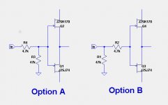
I have noticed all of the FirstWatt designs use the jfet input gate-stopper and input load resistor
shown as Option A below. Why is this done vs. Option B which does not attenuate the input level?
The F6 uses option B. I prefer that one as well, since it minimizes the connections and parasitics at the sensitive gate.
Last edited:
I have noticed all of the FirstWatt designs use the jfet input gate-stopper and input load resistor shown as Option A below. Why is this done vs. Option B which does not attenuate the input level?
When I laid the boards out, sometimes it works out with the resistor to
ground in front, sometimes after the input, probably because it's convenient
and really doesn't matter.
Then I go back and change the schematic.
I can do that. 😉
When I laid the boards out, sometimes it works out with the resistor to
ground in front, sometimes after the input, probably because it's convenient
and really doesn't matter.
Then I go back and change the schematic.
I can do that. 😉
he's doing that sort of things to me ....... all the time

that's probably good thing , laughing is extending Papa's life expectancy

These people show some in stock
Aliexpress.com : Buy SONY 2SK82 V FET from Reliable fet transistors suppliers on Eternal HONG's store | Alibaba Group
No idea if they're authentic, though. Any gamblers here?
According to the vendor they are 2SK82 JA-33 grade.
- Home
- Amplifiers
- Pass Labs
- Sony vFET Amplifier Part 2