must be updated now. 😛
Hi Bangla,
It looks not bad as a starting point - rather compact, just one thing we need to keep in mind - high-current traces (power rails, collectors and emitters of the output transistors, output connection area) need to be wide enough for passing that high current - that requires some extra space.
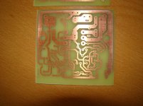
I decided to do just one board for the V1.2. As you can see, iron transfer is not quite as crisp and the photo etch that Thimios uses. Hopefully I will have time tomorrow to transfer the parts over from one of the other boards. I would just do all new but I have running out of red LEDs.
Attachments
Terry,tinning the copper with solder is a simple solution to protect the copper.Thimios,
What do you use to tin the tracks?
Thanks, Terry
Hi Thimios,
That is what I usually do but yours looks like is didn't cover the holes. I have never been that lucky. I usually wait until after I have soldered everything in place. I know there is some kind of solution that will tin the traces but I have not found it.
That is what I usually do but yours looks like is didn't cover the holes. I have never been that lucky. I usually wait until after I have soldered everything in place. I know there is some kind of solution that will tin the traces but I have not found it.
[QUOTEhigh-current traces (power rails, collectors and emitters of the output transistors, output connection area) need to be wide enough for passing that high current - that requires some extra space. ][/QUOTE]
Ah, yes, thanks Valery- will have attention to that.
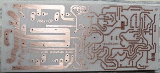
Because "light" limiting size to 100x80mm i can't go wider.
The high of board should be for mounting to 75mm heat sink- my thought.
No i go harder way with Dip Trace library parts doing the same- but than i
have more comfort with placing parts- layout option. 🙂
Terry i use pencil solder iron Multitip 25W, solder with flux and before place
parts- fill tracks short to holes- if you solder parts- fills the rest, that also keeps a bit heat from parts- my opinion.
Thimios could may be much better explain- his more professional looking work.
Ah, yes, thanks Valery- will have attention to that.
Because "light" limiting size to 100x80mm i can't go wider.
The high of board should be for mounting to 75mm heat sink- my thought.
No i go harder way with Dip Trace library parts doing the same- but than i
have more comfort with placing parts- layout option. 🙂
Terry i use pencil solder iron Multitip 25W, solder with flux and before place
parts- fill tracks short to holes- if you solder parts- fills the rest, that also keeps a bit heat from parts- my opinion.
Thimios could may be much better explain- his more professional looking work.
Hi Thimios,
That is what I usually do but yours looks like is didn't cover the holes. I have never been that lucky. I usually wait until after I have soldered everything in place. I know there is some kind of solution that will tin the traces but I have not found it.
You are looking for liquid tin. http://www.mgchemicals.com/products/prototyping-and-circuit-repair/prototyping/liquid-tin-421 Great stuff, and the kids will love turning their pennies into dimes with it. I'd send you a jug, but I don't know how to get it over the boarder.
Another product you might want to try is toner reactive foil. PCB "Fab-In-A-Box" ... The 8min circuit board system This is an iron on product you apply on top of the toner. It leaves a thin layer of graphic product on top of the toner, which seals any porosity in the toner. It gives a much crisper finished product, much like the photoresist boards.
There's a good explanation of this on Pulsar's website. It's worth reading, but you need to sift through the marketing BS. I used their laminator system and toner paper for years with quick and excellent results, but it's expensive. The pouch laminator they used to sell was great. I'm not sure how good their newer ones are.
There are a couple tricks to etching that I used to do with Ferric Chloride. One was to etch with a sponge instead of a big tank. Use a small amount of etchant in a warm glass tray and keep wiping the surface with a sponge soaked in etchant. It etched much faster which reduced undermining the edges.
I thought of another method to make cleanup easier which also gave excellent results. Put the board in a ziplock bag and pour some etchant on it. Squeeze the air out and seal the bag. Double bag it if you want to play safe. Dunk the bag in warm water and rub the surface until the etching is done. This is fast and uses little etchant with great results. I used to do this with 1/2 oz board. I never tried it with 1oz or 2 oz, but I would suspect similar results, but a little slower. It's quite amazing how much you can etch with a small amount of etchant.
Thimios gets great results with the photo resist boards. Terry also has made many very nice boards. I get sometimes usable and sometimes great results using the toner transfer. These came out great. I use a shallow tray and brush the surface of the board while it is etching.
Attachments
Thimios gets great results with the photo resist boards. Terry also has made many very nice boards. I get sometimes usable and sometimes great results using the toner transfer. These came out great. I use a shallow tray and brush the surface of the board while it is etching.
That did come out good! Is that 1/2oz copper? I think the brush would be the same as using a sponge.
Yes, 1/2 oz copper. I tin the tracks when the board gets populated. That little board is probably about as complicated a circuit as I would etch. There is some extra satisfaction in making the pc board as part of the build but commercial boards with the solder mask are easier to solder up not to mention the fact that our home made boards are single layer.
1/2oz comes out great! You can actually do two layer boards quite easily. Use two 1/32" single sided boards and epoxy them together. The vias can be joined with a piece of wire.
I can't be bothered to hand etch any more. After 20 years it's lost it's appeal. JKuetemann showed me the whole board house route and I've never bothered with hand etching again.
I can't be bothered to hand etch any more. After 20 years it's lost it's appeal. JKuetemann showed me the whole board house route and I've never bothered with hand etching again.
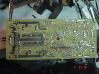
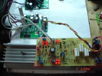
Sons of Vhex ver.1.2
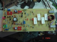
Here is the Sons of vhex ver.1.2
It is up and running.
Now the PSRR is excellent,absolutely quiet,offset is stable,i have a wrong value trimmer installed(100R),so offset is 60mv .
The very first measurements.
Here is the Sons of vhex ver.1.2
It is up and running.
Now the PSRR is excellent,absolutely quiet,offset is stable,i have a wrong value trimmer installed(100R),so offset is 60mv .
The very first measurements.
Attachments
Last edited:
Here is the Sons of vhex ver.1.2
It is up and running.
Now the PSRR is excellent,absolutely quiet,offset is stable,i have a wrong value trimmer installed(100R),so offset is 60mv .
The very first measurements.
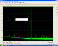
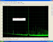
Thimios, this one is looking excellent!

100Hz component is somewhere at -110db - nice.
Right, with 1...2k trimmer you will be able to zero the offset out.
I believe, this one is going to sound very accurate.
The first one was not a waste of time as well - we have learned a few things we have to avoid in the good amplifiers 😛
That was a real design process with great inputs from you and Terry.
Many thanks for all the efforts

Sons of Vhex ver.1.2
Thanks Valery!
I will post more test results later or tomorrow.😉
Let me know if something you want to test.
Thanks Valery!
I will post more test results later or tomorrow.😉
Let me know if something you want to test.
Hi Valery,now it is time for some resistors tuning.Thanks Valery!
I will post more test results later or tomorrow.😉
Let me know if something you want to test.
I know that best way is a matched pairs,matched leds e.t.c but i have two 2sk117 only.🙁
Using a 1K trimmer for offset control i can't go better than 33mV. VAS current is low too.
Using the wrong value offset trimmer(100R) VAS current is 540mV/100R when VAS current trimmer is at the end(Counterclockwise).
Finally the idle current control reach the 20 mV bias when trimmer is at the end(counterclockwise).
Last edited:
Hey thimios,
it is a rather easy test for matching jfets. Only having two will not accomplish a match.
Even your DMM can measure channel resistance as a rough match, similar to Vbe matching.
As simple jig to measure Idss(Vgs=0) and Vpinchoff(Id<1uA) can be made.
I wonder if there are any matched jfets to try, problem is they get expensive. Probably easier to get a bunch of BF862 and put on a small pcb adapter if you are sticking with thole comps.
Last edited:
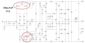
Sorry for delay - just back to my PC.
Thimios, please see attached.
If you've got a 5k trimmer - that would be ideal (R37).
R4, R8 must be 9.1k in this case.
Increasing R10 to 680...750R will allow you setting the VAS idle current to around 6mA.
Note that R37, R4, R8 altogether also influence the VAS current. So the procedure would be:
1) Install R37=5k, R4=9.1k, R8=9.1k;
2) Install R10=680R; Power on with no load, see if you can set the VAS current to 6mA. If it's still too low, change R10 to 750R and try again;
3) Zero-out the offset with R37 - in this configuration it should allow the threshold around -150...+150mV
Cheers,
Valery
Attachments
Ok.Valery i will try your suggestions.Sorry for delay - just back to my PC.
Thimios, please see attached.
If you've got a 5k trimmer - that would be ideal (R37).
R4, R8 must be 9.1k in this case.
Increasing R10 to 680...750R will allow you setting the VAS idle current to around 6mA.
Note that R37, R4, R8 altogether also influence the VAS current. So the procedure would be:
1) Install R37=5k, R4=9.1k, R8=9.1k;
2) Install R10=680R; Power on with no load, see if you can set the VAS current to 6mA. If it's still too low, change R10 to 750R and try again;
3) Zero-out the offset with R37 - in this configuration it should allow the threshold around -150...+150mV
Cheers,
Valery
I have some 2SK146GR DUAL FET but you say that isn't a good solution.
rsavas.I have two pieces 2sk117 only,it is a Valery's donation some time ago.
Last edited:
Ok.Valery i will try your suggestions.
I have some 2SK146GR DUAL FET but you say that isn't a good solution.
rsavas.I have two pieces 2sk117 only,it is a Valery's donation some time ago.
I have just re-checked - I had a bad model. 2SK146 is going to work there.
Although, you can still try to balance it out as is with the latest amendments.
Kudos on a very efficient design vzaichenko, it's hard to get more from less. Has anyone done real world IMD measurements on this amp?
Coming soon.Stay tuned.😉Kudos on a very efficient design vzaichenko, it's hard to get more from less. Has anyone done real world IMD measurements on this amp?
- Home
- Amplifiers
- Solid State
- Sons of VHex