Sons of Vhex
Continue
Continue
Attachments
Last edited:
Thimios and Terry - very valuable information, thanks a lot.
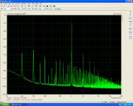
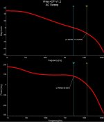
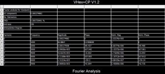
The curves look rather good, although PSRR is not really high here (100Hz component is clearly visible on the spectrums). I did some thinking on the drawbacks revealed and designed a few improvements, eliminating the offset instability, high rails voltage dependency, as well as increasing PSRR and making power-on much smoother - I will publish the improved version shortly.
Most of the components can be re-used, although it will require a new etching.
I will explain in detail the purpose of each change.
Cheers,
Valery
Hi Valery,this amplifier is high sensitive at gnd connection for the inp. stage.Thimios and Terry - very valuable information, thanks a lot.
The curves look rather good, although PSRR is not really high here (100Hz component is clearly visible on the spectrums). I did some thinking on the drawbacks revealed and designed a few improvements, eliminating the offset instability, high rails voltage dependency, as well as increasing PSRR and making power-on much smoother - I will publish the improved version shortly.
Most of the components can be re-used, although it will require a new etching.
I will explain in detail the purpose of each change.
Cheers,
Valery
Using two defferent cables i can see big difference.
Explain more,when i have use a crocodile connection test cable the pumb is big when speaker connected.
When a fast on connection cable was used you can hear nothing when speaker connected.
I have try to power the inp. using capacitance multiplier with worse results.
Strage is that using the capacitance multiplier i see 50 MHz oscillation on the capacitance multiplier rails
I can feel the death of this effort.

Attachments
Last edited:
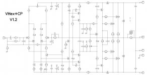
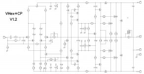
VHex+CP V1.2
Here is the updated schematic.
My sort of mistake with the previous one was using "asymmetric" front-end topology. With such a sensitive super-pair input LTP it leads to rather "slipping" operating points, resulting in the offset drift and overall stability decrease.
This one is fully balanced, with additional filter in LTP for no-compromise stability. Instead of static CCS at the top of the VAS, now it's a current-driven (with mirrors) cascade, forming a truly push-pull VAS. This topology provides much better PSRR and thermal stability of the front-end.
I will publish updated layout tomorrow.
Cheers,
Valery
Attachments

Hi Valery,this amplifier is high sensitive at gnd connection for the inp. stage.
Using two defferent cables i can see big difference.
Explain more,when i have use a crocodile connection test cable the pumb is big when speaker connected.
When a fast on connection cable was used you can hear nothing when speaker connected.
I have try to power the inp. using capacitance multiplier with worse results.
Strage is that using the capacitance multiplier i see 50 MHz oscillation on the capacitance multiplier rails
I can feel the death of this effort.
Do you mean - two cables are not as good as one cable?
Oscillation at the rails with multipliers look kind of strange... well, V1.2 is free from PSRR issue.
No.Do you mean - two cables are not as good as one cable?
Oscillation at the rails with multipliers look kind of strange... well, V1.2 is free from PSRR issue.
1) i have use a crocodile connection test lead for inp. gnd.
In this cace a big pumb was heared when speaker connected (amplifier is already on)
2) a fast on cable used instead of this crocodile connection cable,now you can hear nothing when speaker connected(amplifier is already on)
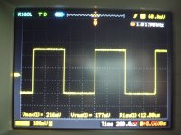
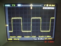
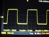
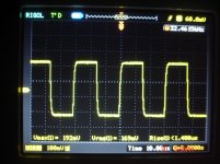
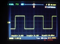
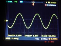
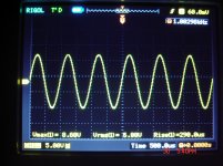
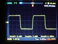
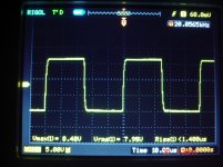
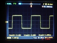
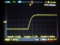
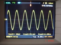
This is the limited testing I did. I first tested with input shorted. Offset wandered a little but not as bad as what Thimios reported. With my sine wave generator connected I saw what looked like a ground issue on the scope, (fat fuzzy line). Sine waves looked ok but the square wave looked perfect at 1khz but ringing at 20k. As I reported, the amp wouldn't start up with a load attached and a light bulb in series with the AC to the transformer. I never tried attaching a speaker. I decided not to go any further since it looked like a losing cause. I'm glad you are coming up with another design. I will await your new layout. I should be able to salvage most of the parts from these boards.
I may just wait on Thimios on the next one since he has much better test equipment and knowledge.
Blessings, Terry
I may just wait on Thimios on the next one since he has much better test equipment and knowledge.
Blessings, Terry
VHex+CP V1.2 Full Package
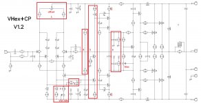
Here we go - updated VHex+CP V1.2 with all the issues of initial design corrected.
As promised, here is what's been done (see the numbered frames on the second picture):
1) As the front-end is symmetric now, DC offset trimmer is places at the top of super-pair-based LTP, adjusting the current ratio in its shoulders;
2) D19, R38 are part of the right shoulder's current mirror. R7 influences common mode DC operation points now, allowing the VAS idle current adjustment;
3) R44, C17 are RC filter, forming the amplitude response curve at the HF, being a part of compensation scheme;
4) R13, R14 values are the same as R15, R16 ones, setting roughly the same current through the voltage reference of LTP's CCS - note, D8, D9 are the red LEDs now. Higher voltage reference provides positive influence on thermal stability of the CCS;
5) Q17, R39 form the right side of the new current mirror, mentioned in (2), Q18 is the common base current follower, reducing the power dissipation of Q17. D7, R40 is the left side of the other asymmetric current mirror (its right side is the VAR transistor Q6);
6) C15, C16 form additional shunt compensation, R41, R42 slightly normalize the input impedance of the driver stage.
Note:
- C8 (lead compensation) value is increased to 4.7pF;
- R17, R18 are 100R.
The reason of much higher PSRR and lower sensitivity to rails voltage fluctuation in general - the balanced nature of the circuit. Now all the common mode signals are heavily suppressed, not only coming to the positive and negative inputs of the amplifier, but virtually everywhere in the front-end.
Let me know if you will have questions.
Cheers,
Valery
Attachments
-
06-VHex+CP-BOTTOM-1.2.pdf50.7 KB · Views: 162
-
05-VHex+CP-TOP-Mirrored-1.2.pdf85.6 KB · Views: 153
-
04-VHex+CP-TOP-1.2.pdf85.6 KB · Views: 167
-
03-VHex+CP-Sch-1.2.pdf52.6 KB · Views: 165
-
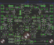
 03-VHex+CP-PCB-1.2.JPG268.8 KB · Views: 215
 -
 01-VHex+CP-TOP-1.2.JPG268.5 KB · Views: 240
 -
 00-VHex+CP-Sch-1.2-markup.jpg224.9 KB · Views: 262
 -
 00-VHex+CP-Sch-1.2.JPG139.6 KB · Views: 252
 -
 VHex+CP V1.2 AC Sweep.jpg61.2 KB · Views: 200
 -
 VHex+CP V1.2 Fourier.jpg110.2 KB · Views: 146
Ok Valery let's go.Dear Thimios, have you got enough courage to try this one? 🙂
Attachments
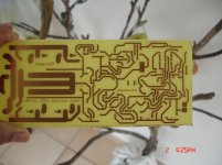


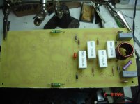
fast... faster...
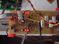
I came tired back from work and look with wide open eyes- what's happen here?
Boaah- thimios with updated board after 8 hrs and partial placed parts. 😱
Tinning the copper with solder i have borrowed for Circlophone boards- thanks.
Thumbs hard pressing that this one will work.
I follow and keep on learning CAD.

- Home
- Amplifiers
- Solid State
- Sons of VHex