Still unbalanced.
First picture immediately after power on.
Second picture 10" later.
Much better.
Now you can zero the offset, increasing R7, R10.
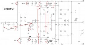
Voltage sensitive VHex+CP
Have learnt a bit more now by following here- all is tricky.
Sorry for stumble with sentiments.
After posts with finished, not full working circuit, again foult numbered diodes.
In schematic we can see D6,7,8,9 are 1N4148 than D10,11,12,13 are RED Led.
Thimios great experienced work to fiddle out the problem- i was following your work in the big NS-OPS.
And:Thanks for good advise Valery and marc to work with CAD.
Eagle light- only good to play with eagle 😕 and nothing else.
I was searching, reading, trying for solution.
Use ULP- Untils- Eagle_to_Dip Trace_SCH..... is not existing there- i can disaggregate my PC- i think, it would not work. 🙁 😱 🙂 😛
Library import is a other chapter, for me to check.
My last try will be to send it to you both.
Have learnt a bit more now by following here- all is tricky.
Sorry for stumble with sentiments.
After posts with finished, not full working circuit, again foult numbered diodes.
In schematic we can see D6,7,8,9 are 1N4148 than D10,11,12,13 are RED Led.
That is cause that i am not clear what is taking about- gives confusion, but have checked now.I'm talking about replacing D6/D7 and D7/D8 with 3.3v zeners.
Thimios great experienced work to fiddle out the problem- i was following your work in the big NS-OPS.
And:Thanks for good advise Valery and marc to work with CAD.
Eagle light- only good to play with eagle 😕 and nothing else.
I was searching, reading, trying for solution.
Use ULP- Untils- Eagle_to_Dip Trace_SCH..... is not existing there- i can disaggregate my PC- i think, it would not work. 🙁 😱 🙂 😛
Library import is a other chapter, for me to check.
My last try will be to send it to you both.
Hi Guys,
I finally got a chance to sit down and do some trouble shooting. I have one board working. I had some bad LED's. Now that I replaced them all of them light. Offset is high at about 142mV with the trimmer maxed at 50R. The lowest I can get the bias is 100mA with the trimmer at 0R. I have not tried passing any sine waves yet but it appears to be working. D4 & D5 are dimmer than the rest.
I finally got a chance to sit down and do some trouble shooting. I have one board working. I had some bad LED's. Now that I replaced them all of them light. Offset is high at about 142mV with the trimmer maxed at 50R. The lowest I can get the bias is 100mA with the trimmer at 0R. I have not tried passing any sine waves yet but it appears to be working. D4 & D5 are dimmer than the rest.
I will try increasing these tomorrow.😉Much better.
Now you can zero the offset, increasing R7, R10.
Hi Guys,
I finally got a chance to sit down and do some trouble shooting. I have one board working. I had some bad LED's. Now that I replaced them all of them light. Offset is high at about 142mV with the trimmer maxed at 50R. The lowest I can get the bias is 100mA with the trimmer at 0R. I have not tried passing any sine waves yet but it appears to be working. D4 & D5 are dimmer than the rest.
Terry, this is good.
Now, can you please increase R10 to, say, 150R - this will move the trimming threshold in the right direction - we need to balance out the thing to some mV.
Then, tell me the voltage across R17, R18 please - we may want to slightly adjust the VAS current.
Yes Terry the same with mine,D4,D5 are dimmer than the rest and dependent by the offset trimming of course.Hi Guys,
I finally got a chance to sit down and do some trouble shooting. I have one board working. I had some bad LED's. Now that I replaced them all of them light. Offset is high at about 142mV with the trimmer maxed at 50R. The lowest I can get the bias is 100mA with the trimmer at 0R. I have not tried passing any sine waves yet but it appears to be working. D4 & D5 are dimmer than the rest.
Powering the amplifier these D4,D5 are dark,they lights later.
Terry,have you power on the completely amplifier or the up to the vas version?
Ha
Use ULP- Untils- Eagle_to_Dip Trace_SCH..... is not existing there- i can disaggregate my PC- i think, it would not work. 🙁 😱 🙂 😛
Library import is a other chapter, for me to check.
My last try will be to send it to you both.
Check your mail box.
Marc
Yes Terry the same with mine,D4,D5 are dimmer than the rest and dependent by the offset trimming of course.
Powering the amplifier these D4,D5 are dark,they lights later.
Terry,have you power on the completely amplifier or the up to the vas version?
I powered the whole amp. I used my variac to set the rails to +-50V. One board still has issues but I will deal with that when I get this board set properly.
Valery, give me about an hour and I will have it for you.
What is the goal for vas current?Terry, this is good.
Now, can you please increase R10 to, say, 150R - this will move the trimming threshold in the right direction - we need to balance out the thing to some mV.
Then, tell me the voltage across R17, R18 please - we may want to slightly adjust the VAS current.
OK, replacing R10 with 150R is good. I can now zero the offset. R17,R18 are 658mV.
OK, cool - the VAS current is around 8.8mA - a bit higher than expected.
But let's leave it for now (other wise we may have to re-set the offset again).
100-110mA per output pair will be good. You can slightly increase R21 (620R) or switch to 200R trimmer (R19) if you want to be able to set lower bias.
Looking good! 🙂
It is a pleasure to follow along and witness a design team, in different parts of the world working together.
Cheers guys
Cheers guys
It is a pleasure to follow along and witness a design team, in different parts of the world working together.
Cheers guys
Thank you Rick! 🙂
Yes, we don't care about the distances - planet Earth is the one we're living on 😀
OK, cool - the VAS current is around 8.8mA - a bit higher than expected.
But let's leave it for now (other wise we may have to re-set the offset again).
100-110mA per output pair will be good. You can slightly increase R21 (620R) or switch to 200R trimmer (R19) if you want to be able to set lower bias.
Looking good! 🙂
Actually I misspoke earlier. I actually have a 200R trimmer installed because I was out to 100R. The trimmer is maxed out at 200R and the bias is at 100mA. I will try a higher value for R21 and see if I can get it down some. I know 100mA is OK but it is good to have some adjustment.
You can pad the value with an added resistor that will extend the range without giving you a touchy control.
-Chris
-Chris
Sons of Vhex
I have instal new values R10=150R,R17,R18=100R and here is what i measure.
Now offset is 0v but it isn't stable. This vary continuously from 0 up to 15 mv
VAS current(using R17,R18=100R) is 6.5mA.
I have instal new values R10=150R,R17,R18=100R and here is what i measure.
Now offset is 0v but it isn't stable. This vary continuously from 0 up to 15 mv
VAS current(using R17,R18=100R) is 6.5mA.
Attachments
Last edited:
I installed 150R for R10, 620R for R21 and 200R trimmer for bias. Everything is working well now. The offset does wander slightly. I bypassed my variac and the rails dropped to +-44V. Everything still looks good but I had to readjust the offset. Seems it's rail sensitive. I'll get it hooked up to the scope a little later.
- Home
- Amplifiers
- Solid State
- Sons of VHex