I’m using a EE Minimax with discrete I/V (sparkolabs) into a medium-mu, dual triode (12au7). Amazing way to feed any amp.
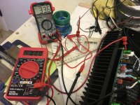
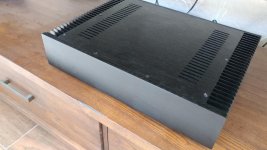
VHEX biased at ~33.5mv, offset came right out. Very good design. Ground loop breaker was accomplished with a CL-60 in series between clean and dirty ground, one star for each channel.
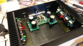
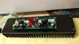
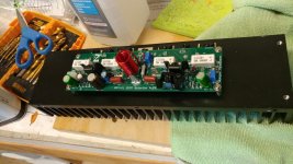
This amplifier continues to amaze me with incredible performance. I did Some boutique parts, but only in the signal path (Simics, Nichicon KG). Cardas bonding posts.
Capacitors are passive devices, therefore, they do not have as much impact as active ones, but they do make a small difference.
Nichicon, low ESR, high ripple caps were used in the PSU boards.
This amplifier does everything well. The toughest thing for any system are female voices. I’ve tried the hardest recordings and with my somewhat soft tube dac, female voices are rendered with incredible depth, resolution and beauty.
I listen to every type of music, I mean every type. This amp is such a good, all around, performer. However, It’s meaningless to cite albums you’ve never heard, let alone never heard in my listening room.
This amp is a sonic blockbuster. Bias-wise, it takes about 20 minutes for the amp to reach stability. However, the sonic difference between cold and warmed up is not that much. I usually preheat heatsinks with hot air prior to biasing but with this amp I did not. First bias at 10 minutes, second one at 20 minutes. Last at an hour.
It’s detailed, resolving and drives my Martin Logan Montis with authority!
Now I need to finish my USSA-5, class A and compare the two! After that I’ve got the Alpha20. I have a feeling that the VHEX is going to be as good, different of course, but with more power.
Today, half-wave vs full-wave designs are very close. Don’t hesitate to build the VHEX!
VHEX biased at ~33.5mv, offset came right out. Very good design. Ground loop breaker was accomplished with a CL-60 in series between clean and dirty ground, one star for each channel.
This amplifier continues to amaze me with incredible performance. I did Some boutique parts, but only in the signal path (Simics, Nichicon KG). Cardas bonding posts.
Capacitors are passive devices, therefore, they do not have as much impact as active ones, but they do make a small difference.
Nichicon, low ESR, high ripple caps were used in the PSU boards.
This amplifier does everything well. The toughest thing for any system are female voices. I’ve tried the hardest recordings and with my somewhat soft tube dac, female voices are rendered with incredible depth, resolution and beauty.
I listen to every type of music, I mean every type. This amp is such a good, all around, performer. However, It’s meaningless to cite albums you’ve never heard, let alone never heard in my listening room.
This amp is a sonic blockbuster. Bias-wise, it takes about 20 minutes for the amp to reach stability. However, the sonic difference between cold and warmed up is not that much. I usually preheat heatsinks with hot air prior to biasing but with this amp I did not. First bias at 10 minutes, second one at 20 minutes. Last at an hour.
It’s detailed, resolving and drives my Martin Logan Montis with authority!
Now I need to finish my USSA-5, class A and compare the two! After that I’ve got the Alpha20. I have a feeling that the VHEX is going to be as good, different of course, but with more power.
Today, half-wave vs full-wave designs are very close. Don’t hesitate to build the VHEX!
Attachments
Last edited:
Greg's build is awesome 
Careful approach with attention to every detail is rewarding 🙂
Great job!
Careful approach with attention to every detail is rewarding 🙂
Great job!
I know they are just an approximation of what the amp might be, but are there any asc files to look at for this amp?
I use Multisim for simulations, so I've got only .ms14 files. I can share them with you if you can use Multisim.
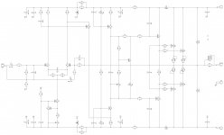
Here is the exact schematic of the amplifier:
VHex+
For the boards and everything else - please see my signature below.
That schematic in Post 88 is missing two bypass capacitors between R20 and R12, and R21 & R13 !
That schematic in Post 88 is missing two bypass capacitors between R20 and R12, and R21 & R13 !
Actually, you're right - 2 caps are missing there, I didn't notice that.
Here is the full version with those caps in place (C14, C15).
Cheers,
Valery
Attachments
OK, the LTSpice sim is ready, or quite.
I need to know the power supply voltage, the bias current and the LTP ccs current too.
Then I can upload the asc files to those that would like to run it.
I need to know the power supply voltage, the bias current and the LTP ccs current too.
Then I can upload the asc files to those that would like to run it.
Power supply voltage is +/- 48. Bias current is 85mA. Set the current in the front end so DC offset is zero on the output.
OK, here's the V-Hex sim.
Except for the bode plot, which does not seem to fulfill the stability requirements, THD and Square Wave look quite good I think.
The Models I used are all Cordell's, which probably other LTSpice users have.
I'm relatively new to LTSpice, so more experienced users are welcome to try the files and run them. And please do tell me what are your findings.
One thing I have wondered, since I knew about the potential stability Bode plots show, is how does it manifest itself.
If amps have already been built with this schematic, and they work fine, then something should be wrong on the simulations. And I would certainly like to know about that.
Attachments
Hi Carlmart,
In order to see the stability margins, you need to analyze not the amplifier's bode plot, but the feedback loop bode plot. Normally, the Tian probe is used for that purpose in LTspice.
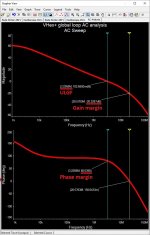
1-st picture is what the feedback loop analysis shows (Multisim presentation):
- gain margin = 20db;
- phase margin = 80 degrees.
2-nd picture shows the key currents in IPS-VAS sections.
Rails voltage for "as-is" configuration is +/-48...52V DC.
Driver stage idle current is 12mA, output transistors' idle current is 80mA per each output pair - roughly 36mV across 2 x 0.22R resistors in series.
Cheers,
Valery
P.S. It's important to set the trimmers in your sim in the right positions for having zero offset and 80mA idle current per output pair for the sim to show the right results.
In order to see the stability margins, you need to analyze not the amplifier's bode plot, but the feedback loop bode plot. Normally, the Tian probe is used for that purpose in LTspice.
1-st picture is what the feedback loop analysis shows (Multisim presentation):
- gain margin = 20db;
- phase margin = 80 degrees.
2-nd picture shows the key currents in IPS-VAS sections.
Rails voltage for "as-is" configuration is +/-48...52V DC.
Driver stage idle current is 12mA, output transistors' idle current is 80mA per each output pair - roughly 36mV across 2 x 0.22R resistors in series.
Cheers,
Valery
P.S. It's important to set the trimmers in your sim in the right positions for having zero offset and 80mA idle current per output pair for the sim to show the right results.
Attachments
![[Amp-design-01] 2018-04-15 01-35-50.jpg](/community/data/attachments/610/610397-2d6bae7f65a1a2a705ec7f59e77369ee.jpg?hash=LWuuf2Whoq)
Last edited:
Valery,
First of all you should know that my knowledge of LTSpice is limited, I am learning how to use it. That's why I uploaded the asc files for anyone who knows more to run them.
The bias trimmer I had set for the current you told me (85mA), though I didn't know it was for each pair. The total idle current now, after readjustment, turns out to be 197mA. Each MOSFET has to dissipate 3.84 W. Is that correct?
The DC offset is 286uA with the trim I used, which is quite close to zero.
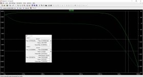
THD @ 1KHz is 0.00075%, which is very good, at 95W into 8 ohms, using +/-48v.
I do not know how to use the Tian probe, so I would love to have someone show me how to, and how to read the results.
First of all you should know that my knowledge of LTSpice is limited, I am learning how to use it. That's why I uploaded the asc files for anyone who knows more to run them.
The bias trimmer I had set for the current you told me (85mA), though I didn't know it was for each pair. The total idle current now, after readjustment, turns out to be 197mA. Each MOSFET has to dissipate 3.84 W. Is that correct?
The DC offset is 286uA with the trim I used, which is quite close to zero.
THD @ 1KHz is 0.00075%, which is very good, at 95W into 8 ohms, using +/-48v.
I do not know how to use the Tian probe, so I would love to have someone show me how to, and how to read the results.
Valery,
First of all you should know that my knowledge of LTSpice is limited, I am learning how to use it. That's why I uploaded the asc files for anyone who knows more to run them.
The bias trimmer I had set for the current you told me (85mA), though I didn't know it was for each pair. The total idle current now, after readjustment, turns out to be 197mA. Each MOSFET has to dissipate 3.84 W. Is that correct?
The DC offset is 286uA with the trim I used, which is quite close to zero.
THD @ 1KHz is 0.00075%, which is very good, at 95W into 8 ohms, using +/-48v.
I do not know how to use the Tian probe, so I would love to have someone show me how to, and how to read the results.
Yes, dissipation of around 3.5W for each HexFET at idle is about right - you've got it a bit higher because of the higher bias now, but that's ok anyway. I have checked my live prototype - I used 80mA per output pair in it. In this case total for 2 pairs = 160mA, dissipation is 3.27W per HexFET.
Yes, the amplifier is very good in terms of both the measured distortion and the way it sounds. It's also very quiet and immune to external EMF (fluorescent lamps, transformers, etc). We have tested (and sometimes abused 🙂) the prototype in many different situations - a properly built VHex+ shows a steady performance in all the situations. I have to mention that we normally equip the build with the "21-st century" control board, protecting both the speakers and the amp from damage in case of too much of abuse 😛
I'm also not too much versed in using LTSpice as I historically use Multisin for many years and am quite happy with it 🙂
Can some LTSpice guru help to insert the Tian probe into the sim to see the loop gain/phase, please? It's going to be a useful LTSpice lesson for me as well 🙄
To measure phase margin and gain margin with LTSpice using the Tian's Method:
. No signal input
. Insert a Voltage Source and a Current Source in the feedback path as in the attached .asc file
. Define AC analysis from 1 to 100MHz .ac oct 500 1 100Meg
. Add spice directive .step param prb list -1 1
. Run simulation and plot this expression:
-1/(1-1/(2*(I(Vi)@1*V(x)@2-V(x)@1*I(Vi)@2)+V(x)@1+I(Vi)@2))
I have also attached the plot setting file (rename .txt to .plt) with the above defined expression, so if you run the simulation you have the result directly.
In this case phase margin is 75° and gain margin is 18dB and so in normal use (closed loop) the amplifier will be stable.
Attachments
Last edited:
To measure phase margin and gain margin with LTSpice using the Tian's Method:
. No signal input
. Insert a Voltage Source and a Current Source in the feedback path as in the attached .asc file
. Define AC analysis from 1 to 100MHz .ac oct 500 1 100Meg
. Add spice directive .step param prb list -1 1
. Run simulation and plot this expression:
-1/(1-1/(2*(I(Vi)@1*V(x)@2-V(x)@1*I(Vi)@2)+V(x)@1+I(Vi)@2))
I have also attached the plot setting file (rename .txt to .plt) with the above defined expression, so if you run the simulation you have the result directly.
In this case phase margin is 75° and gain margin is 18dB and so in normal use (closed loop) the amplifier will be stable.
Many thanks Giancarlo!
Although I've got the "pot" symbol unknown and all the transistor models used here are missing in my Cordell-Models.txt

- Home
- Amplifiers
- Solid State
- Sons of VHex