I'm glad we seem to be getting somewhere on what we mean to say.
Now I'm eager to know how to handle the Tyan probe on other amps I was working with that seemed to be unstable. Particularly how to diagnose that by looking at the curves.
How do I get to get a plt file? I've changed the parameters on my asc file to Giancarlo's, but the plt file seems to be essential. But just renaming Giancarlo's plt file does not get his results and screen.
I use simple method to plot the Loop Gain and you don't need plt file.
If you open my .asc file in the lower left corner you ca see spice directives:
.step param prb list -1 1 ; set prb=0 to turn off probe
;.par prb=0
and one text:
-1/(1-1/(2*(I(Vi)@1*V(x)@2-V(x)@1*I(Vi)@2)+V(x)@1+I(Vi)@2))
Just run .ac and plot anything (I just plot vout) and then change it to the text above.
BR Damir
Hi Damir,
A valid option, however, I like to keep compensation as "light" as possible.
Lender configuration ensures a better phase response than a "regular" common-emitter VAS, so a simple RC at the left collector of LTP is enough for shaping the phase response, ensuring the loop stability.
Cheers,
Valery
Hi Valery,
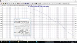
I suppose by "light" you meant simple. I prefer to keep distortion level similar as possible up to 20 kHz, and that by making LG bandwidth as large possible. This amp has medium high feedback and here is its LG plot with OITPC.
Probably is possible to optimize this OITPC, I did quick simulation only.
Regards
Damir
Attachments
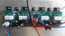
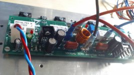
Run tests these days on VHex+.
First, the bias is right on the spot from the time i switch the power on till the heat sinks reach 50 degrees Celsius. Rock stable. Also the offset is easy to set.
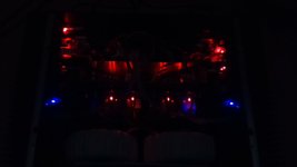
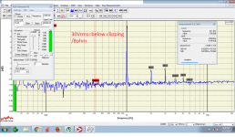
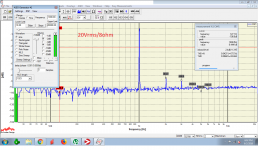
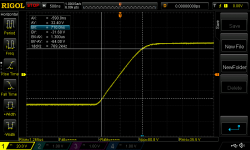
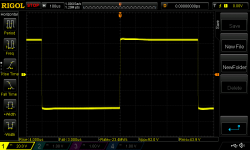
Square wave is perfect. All measurements are made at +/-53Volts with 8ohm load.
Very nice good sounding little amp!
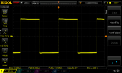
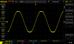
Last two pictures are from TubSuMo.
First, the bias is right on the spot from the time i switch the power on till the heat sinks reach 50 degrees Celsius. Rock stable. Also the offset is easy to set.
Square wave is perfect. All measurements are made at +/-53Volts with 8ohm load.
Very nice good sounding little amp!
Last two pictures are from TubSuMo.
Attachments
-
 DSC_0215.jpg252.3 KB · Views: 265
 -
 DSC_0212.JPG479.9 KB · Views: 251
 -
 Untitled1.png100.3 KB · Views: 260
 -
 Untitled.png98.4 KB · Views: 254
 -
 NewFile4.png39.9 KB · Views: 197
 -
 NewFile3.png33.7 KB · Views: 191
 -
 NewFile2.png35.9 KB · Views: 591
 -
 NewFile1.png38.1 KB · Views: 619
 -
 DSC_0005.jpg265.4 KB · Views: 604
 -
 DSC_0001.jpg256.5 KB · Views: 620
Run tests these days on VHex+.
First, the bias is right on the spot from the time i switch the power on till the heat sinks reach 50 degrees Celsius. Rock stable. Also the offset is easy to set.
Square wave is perfect. All measurements are made at +/-53Volts with 8ohm load.
Very nice good sounding little amp!
Last two pictures are from TubSuMo.
Nice build

Clean clipping and excellent harmonics profile with virtually no high-order components.
You did it right! 😀
Hi Valery, can you point out the optimal ground connections power supply and speaker out?
I took it from the power supply ground but I have a light buzz
I took it from the power supply ground but I have a light buzz
Run tests these days on VHex+.
First, the bias is right on the spot from the time i switch the power on till the heat sinks reach 50 degrees Celsius. Rock stable. Also the offset is easy to set.
Square wave is perfect. All measurements are made at +/-53Volts with 8ohm load.
Very nice good sounding little amp!
Last two pictures are from TubSuMo.
Nice psu, nice build. That’s what I need to do on my build is go dual mono.
Hi Valery, can you point out the optimal ground connections power supply and speaker out?
I took it from the power supply ground but I have a light buzz
What psu setup are you using?

What works for one build may not work for another: Grounding schemes are really unique per build but what you want is if dual mono psu is a completely separate star with ground loop breaker. I just use a CL-60 or other thermistor of close to same R.
When I build a new amp I just user jumpers to add or remove items to the star.
Hi Valery, can you point out the optimal ground connections power supply and speaker out?
I took it from the power supply ground but I have a light buzz
Hi Patriz,
Here is an excellent article on the amplifier wiring by Andrew Russel:
http://hifisonix.com/wordpress/wp-content/uploads/2018/07/How-to-wire-up-an-amplifier_3.pdf
T-ground is an excellent approach. I used it in my CF-FET V2.0 amplifier with the excellent result - dead silent amplifier.
The most critical area is the inputs grounding.
Cheers,
Valery
It means that when you have separate secondaries, you have to use another bridge?
Is that an earth lifter?
The T is solid copper or a piece of pcb? I guess it's the former, because of the thickness, or else a pcb with lots of solder covering the whole surface.
The 1nF ceramic cap trick by the inputs, linking in ground to nearby chassis, does what? I mean what happens if we don't put the cap and just use the 10-15 ohm resistor at the input for the audio ground?
Hi Carlmart, below are my answers:
It's not that you have to, but separate bridges will give better results.
Ground lift is a powerful loop-breaking technique but that 2-nd rectifier is not related to it. It's just a separate rectifier for the other secondary.
For a power amplifier, it's a solid piece of copper. Some low-power applications, like a preamp, can have it as part of PCB.
Page 49 of the document. RF interference cancellation.
Cheers,
Valery
It means that when you have separate secondaries, you have to use another bridge?
It's not that you have to, but separate bridges will give better results.
Is that an earth lifter?
Ground lift is a powerful loop-breaking technique but that 2-nd rectifier is not related to it. It's just a separate rectifier for the other secondary.
The T is solid copper or a piece of pcb? I guess it's the former, because of the thickness, or else a pcb with lots of solder covering the whole surface.
For a power amplifier, it's a solid piece of copper. Some low-power applications, like a preamp, can have it as part of PCB.
The 1nF ceramic cap trick by the inputs, linking in ground to nearby chassis, does what? I mean what happens if we don't put the cap and just use the 10-15 ohm resistor at the input for the audio ground?
Page 49 of the document. RF interference cancellation.
Cheers,
Valery
Hi Valery,
I meant the third bridge on the schematic, the one used for the ground. I had never seen that or a ground lift, and I'm curious about it.
The two bridges, one for each secondary I knew about and it seems to be a very good thing for a better star ground, noise and hum wise.
I meant the third bridge on the schematic, the one used for the ground. I had never seen that or a ground lift, and I'm curious about it.
The two bridges, one for each secondary I knew about and it seems to be a very good thing for a better star ground, noise and hum wise.
Hi Valery,
I meant the third bridge on the schematic, the one used for the ground. I had never seen that or a ground lift, and I'm curious about it.
The two bridges, one for each secondary I knew about and it seems to be a very good thing for a better star ground, noise and hum wise.
Ah, ok - I see. That's the right way of connecting the main PSU ground to the chassis - pages 54, 55 of the document. A single point connection through the bridge.
I've done quite a bit of experimenting with power supplies on the VHex series of amplifiers. I've never found any need for anything more than a basic pair of capacitors in the supply (no CRC, ect). There is a noticeable improvement in the sound stage when running a separate supply for each channel though. Following the schematic ggetzoff posted will give you a dead silent excellent sounding stereo amplifier.
Hi Valery,
I meant the third bridge on the schematic, the one used for the ground. I had never seen that or a ground lift, and I'm curious about it.
The two bridges, one for each secondary I knew about and it seems to be a very good thing for a better star ground, noise and hum wise.
If you're referring to D1 and D2 in the schematic ggetzoff posted, those are standard ground loop breakers. The supplies are meant to remain isolated from each other so each requires it's own loop breaker. Rod Elliot has a good page on his website explaining them Earthing (Grounding) Your Hi-Fi - Tricks and Techniques
- Home
- Amplifiers
- Solid State
- Sons of VHex