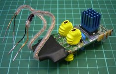
I have just finished rebuilding an old board with some new inductors that Lee (Lostcause), supplied the cores, thanks again Lee.
I copied Lee's idea of keeping one of the legs of each of the inductors long enough to go straight to the speaker terminals. A nice direct path for the output.
The C10 power Cap lays flat under the board and connects directly to the pos' side of the two 0.1uf, C11 & C12 Caps and the large ground area.
I'll see how it sounds later..
PS, you must remove the lacquer from the inductor wire were it passes through the board so that the filter cct is still connected.
Attachments
audio1st said:I have just finished rebuilding an old board with some new inductors that Lee (Lostcause), supplied the cores, thanks again Lee.
I copied Lee's idea of keeping one of the legs of each of the inductors long enough to go straight to the speaker terminals. A nice direct path for the output.
The C10 power Cap lays flat under the board and connects directly to the pos' side of the two 0.1uf, C11 & C12 Caps and the large ground area.
I'll see how it sounds later..
PS, you must remove the lacquer from the inductor wire were it passes through the board so that the filter cct is still connected.
Nice job Barry, love the yellow jackets, they look cool!😎
Tidy job on the outputs as well.
What's happening on the right side of the board? are they the inputs and ground?
Is this board going into your Bottle stop sculpture?
Lee
Lostcause said:
What's happening on the right side of the board? are they the inputs and ground?
Is this board going into your Bottle stop sculpture?
Lee
Yes Lee, they are the L, R and Ground.
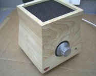
An no, it's not going in the Bottle stop sculpture, with the nice wallpaper behind it, it is already back in it's "sugar cannistor" and sounding fabulous....
Cheers Barry..😉
Attachments
audio1st said:
Yes Lee, they are the L, R and Ground.
An no, it's not going in the Bottle stop sculpture, with the nice wallpaper behind it, it is already back in it's "sugar cannistor" and sounding fabulous....
Cheers Barry..😉
That's the dogs b0ll0cks!
You sure like to make em unusual!...individual!
What do you think of the sound against the stock bobbins?
dranreb&* said:thus the c10 stuck cap be replaced or just parallel the stiffener cap to the stuck one.thanks
OK, just to make sure that you ar aware:
If you jump the power straight to the cap then the switch will not work and it will be always ON. The switch will just allow power to the LED.
If you do decide to power onto the cap then go directly to it, dont bother jumping.
If you do decide to do this then you should replace C10 for a better/bigger/lower ESR cap whilst you are at it. If your going this far you might as well get the full benefit of well filtered power!
Happy modding
Lee
It is best to replace C10 with a better cap. The stock cap is not very good. Just adding another cap will give you more reserve, but won't eliminae the distortion caused by the original cap.
audio1st said:
Yes Lee, they are the L, R and Ground.
An no, it's not going in the Bottle stop sculpture, with the nice wallpaper behind it, it is already back in it's "sugar cannistor" and sounding fabulous....
Cheers Barry..😉
Hold on a sec...have'nt I seen that box before?
BOX
That's the one
follow up to my previous question can I replaced c10 with 6800uf cap, I have a stuck somewhere here. thanks for your helpfull reply😉
Puffin said:I have just added a BHC Aerovox 4700uf as a stiffener cap (very large size can 4" by 1 1/2 half diameter) as suggested by lostcause. Wow did someone replace the 6-7 watts per channel with a Krell! S.I on steroids. I am amazed. I have a 6800uf one spare ??
Are you guys adding the big stiffeners using SMPS or linear psus? I mean, doesn't a 470uF @ 20kHz (conservative guess) = 94,000uF @ 100Hz?
(470uF is the biggest 8mm low-ESR I have)
Originally posted by motherone (post#1)
This information is based on a Sonic Impact 5066 board with the date code of 2003.07.03
=============
Connector #1:
=============
(from Left to Right):
V + Ro Lo G Li Ri
V = switch 12volt out
+ = switch 12volt in
Ro = to volume from right channel
Lo = to volume from left channel
G = ground
Li = from volume control to amp left channel
Ri = from volume control to amp right channel
I found that a bit confusing. On my board (Rev.A0, 2005.09.07) and from Audio1st's stealth-mod pic, Conn#1 goes
#1 switch (red wire)
#2 switch
#3 R wiper (ie, from vol pot to amp)
#4 L wiper
#5 ground ends of vol pot
#6 L input socket to vol pot (stock jack)
#7 R input socket to vol pot (stock jack)
Posts 55-58 maybe mention this. 😕
Bigger is better, right?
Cpemma,
It would seem on the surface that what you observed is correct however there are a lot of other factors involved. The main one is that this is an audio amp and delivers power at audio frequencies. In order for the amp to see a low source impedance at these frequencies it must be drawing current from a large cap. Of course the SMPS regulation circuit will be there and make corrections but this is after the fact. Also some supplies will let the voltage drop as much as ½ volt before responding due to limited loop gain.
I am using 18,000 uf in my amp 3 setup and have used 33,000 uf where space permits. This gives you a solid bass presentation far beyond what you would expect from these little amps. It is also a quieter source with all this filtering and gives you a really deep sound stage.
Roger
cpemma said:
Are you guys adding the big stiffeners using SMPS or linear psus? I mean, doesn't a 470uF @ 20kHz (conservative guess) = 94,000uF @ 100Hz?
(470uF is the biggest 8mm low-ESR I have)
Cpemma,
It would seem on the surface that what you observed is correct however there are a lot of other factors involved. The main one is that this is an audio amp and delivers power at audio frequencies. In order for the amp to see a low source impedance at these frequencies it must be drawing current from a large cap. Of course the SMPS regulation circuit will be there and make corrections but this is after the fact. Also some supplies will let the voltage drop as much as ½ volt before responding due to limited loop gain.
I am using 18,000 uf in my amp 3 setup and have used 33,000 uf where space permits. This gives you a solid bass presentation far beyond what you would expect from these little amps. It is also a quieter source with all this filtering and gives you a really deep sound stage.
Roger
cpemma said:470uF is the biggest 8mm low-ESR I have
470uF onboard is just fine. It is the offboard cap that can be much bigger.
hi panomaniac,
i am using a 5.2A SMPS on a charlize amp. want to add a stiffener cap but has not yet read a YES/NO reply using an SMPS.
can a stiffener cap be used with an SMPS?
cheers🙂
i am using a 5.2A SMPS on a charlize amp. want to add a stiffener cap but has not yet read a YES/NO reply using an SMPS.
can a stiffener cap be used with an SMPS?
cheers🙂
Hi, Lostcause. Thank you for the information as to alternative places to connect if you screw-up at R1 and R2. The photograph doesn't show clearly where C5 is meant to go. Do you connect it between the new connection holes or on the pins of the chip, if so which pins ? I assume also that R1 and R2 are removed.
Puffin said:Hi, Lostcause. Thank you for the information as to alternative places to connect if you screw-up at R1 and R2. The photograph doesn't show clearly where C5 is meant to go. Do you connect it between the new connection holes or on the pins of the chip, if so which pins ? I assume also that R1 and R2 are removed.
Hi Puffin,
OK so.....R5 is moved between the through holes so it can go top or bottom. Here is a CAD view of where I put it, no pictures sorry, that T is with a mate.
I've removed the other components to make it clear.
If you are going to move R5 then you might as well replace it with R2, a lower value. Then you just need to swap R1 for R4 then put in the 20K leaded resistors.
Leaded resistors first, then the SMT's.
Cheers
Lee
Attachments
weng said:can a stiffener cap be used with an SMPS?
YES. I do it all the time. Works well.
Bulk storage cap problem.
I also have had no problem even with very large caps on smallish (< 2 amps) 12v supplies. I have had problems with larger higher voltage supplies. The supply shuts down due to over current on startup and takes several cycles to get the cap charged enough to stay on. This required a cap change to allow more starting current for long enough to start successfully. With this done they worked beautifully. Just wanted you to be aware this doesn’t always work with out problems.
Roger
panomaniac said:
YES. I do it all the time. Works well.
I also have had no problem even with very large caps on smallish (< 2 amps) 12v supplies. I have had problems with larger higher voltage supplies. The supply shuts down due to over current on startup and takes several cycles to get the cap charged enough to stay on. This required a cap change to allow more starting current for long enough to start successfully. With this done they worked beautifully. Just wanted you to be aware this doesn’t always work with out problems.
Roger
might sound stupid but is the connection for the stiffener cap to the smps in parallel? meaning +pin goes to +12v and -pin goes to gnd?
japjag said:is the connection for the stiffener cap to the smps in parallel?
Correct!
And if you install a soft start circuit, you will not have the PSU over current shut down. The power supply likes the soft start, too. 🙂
- Status
- Not open for further replies.
- Home
- Amplifiers
- Class D
- Sonic Impact 5066 Parts List & Modifications