dorkus said:...what happened to HPotter?
He almost left the building.😉
http://www.diyaudio.com/forums/showthread.php?s=&postid=46563#post46563
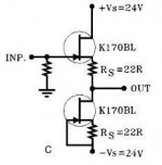
Jfet buffer
Add source resistor to the to upper Jfet in following......
The cap value is not critical and can be smaller with 1 Meg resistor value increased to a couple of Meg for lower freguency cutoff. I would put 221 ohm gate damping resistors on both Jfets.
Add source resistor to the to upper Jfet in following......
The cap value is not critical and can be smaller with 1 Meg resistor value increased to a couple of Meg for lower freguency cutoff. I would put 221 ohm gate damping resistors on both Jfets.
Attachments
adjusting source resistors
harry, i tried adjusting the source resistor on the top JFET by putting another resistor in parallel, and it did help lower offset but not by a lot, and i was a little afraid of deviating too much from the 22 ohm nominal value... but i just realized it doesn't really matter what the exact value of that resistor is as long as it's not too high, right? i will play around with the values to see if i can get the offset nice and low.
i think i would rather increase the feedback capacitance than increase the 1M ohm resistor at the bottom to keep the LF cutoff suitably low, in general i don't like to make any impedances too high (more noise?).
oh yeah, i am using a 1k resistor on the gates... too high? 220 ohms seems to be a popular value, but i remember you talking about how you can "voice" the sound of the circuit by changing gate dampening. i will have to check it out...
p.s. what's a good amount of bias current for this circuit? borbely specifies BL-grade in his schematic but i have GR. i guess i will have to adjust the top drain resistor.
i guess i will have to adjust the top drain resistor.
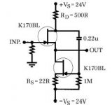
The bias current is a function of the source resistors. I think you could go down to 10 or 15 ohms for green bias group Jfets. 1K is probably fine for gate resistors. The drain resistor controls open loop gain and making it larger will increase the amount of negative feedback and making it smaller will decrease the amount of negative feedback. Closed loop gain is 1. I would keep the DC voltage across the Jfets between 10 and 20 volts for low noise and good bandwidth. The circuit really doesn't need 24 volt supplies and should wourk fine with 15 to 20V supplies. The negative supply could be 5 volts less than the positive if desired since the bottom JFet doesn't have the voltage drop from a drain resistor.
H.H.
A commitee of one. (Hey it makes as much sense as an army of one.....)
If you use the double fets from TOshiba than normally you won´t get any offset. 2SK389 and 2SJ109 they are n and p type double fets. You can find more info in borbeley´s site.
or here :
http://www.schuro.de/Daten/Japanhalbleiter/2SK389.pdf
http://www.schuro.de/Daten/Japanhalbleiter/2SJ109.pdf
they are expensive but worth it if you don´t use caps.
or here :
http://www.schuro.de/Daten/Japanhalbleiter/2SK389.pdf
http://www.schuro.de/Daten/Japanhalbleiter/2SJ109.pdf
they are expensive but worth it if you don´t use caps.
Duals
What happened to also monolithic duals 2SK240 and 2SJ75? Were they discontinued? Weren't they cheaper?
Are there any USA sources for dual MOSFETs? The only I know is Audio Lab of Georgia, but they have very small stocks.
Carlos
What happened to also monolithic duals 2SK240 and 2SJ75? Were they discontinued? Weren't they cheaper?
Are there any USA sources for dual MOSFETs? The only I know is Audio Lab of Georgia, but they have very small stocks.
Carlos
Re: Duals
the k240/j74 are no longer in production ... also they were not monolithic but rather 2 individual matched fets mounted in a single aluminium casing.
carlmart said:What happened to also monolithic duals 2SK240 and 2SJ75? Were they discontinued? Weren't they cheaper?
Are there any USA sources for dual MOSFETs? The only I know is Audio Lab of Georgia, but they have very small stocks.
Carlos
the k240/j74 are no longer in production ... also they were not monolithic but rather 2 individual matched fets mounted in a single aluminium casing.
double fets from TOshiba
I don't think this will work since the dual fets have a common substrate electrical connection. You really should be able to get very low offset by adjusting the source resistors with the K170s.
H.H.
I don't think this will work since the dual fets have a common substrate electrical connection. You really should be able to get very low offset by adjusting the source resistors with the K170s.
H.H.
oh whoops, right. source resistors, not drain, determine the bias. i have not measured anything yet but i will check soon and post my results. i still need to check the possible oscillation in my regulator too, but alas my girlfriend is visiting this week so i'm not sure when i'll get to it...
see harry
this design-by-commitee thing is not so bad. you call the shots, i try stuff out and arbitrate the discussion. not exactly a commitee but whatever. 😛
this design-by-commitee thing is not so bad. you call the shots, i try stuff out and arbitrate the discussion. not exactly a commitee but whatever. 😛
whoops
harry was right... for green bias rated SK170's, 22 ohm source resistors are too big. i measured measly bias currents of 3.5mA in one channel, 2.7mA in the other. i am playing with some the values now to try to boost that up a lot, i figure i will want at least 10mA or so, and in the process i will try nulling the output offset as well. the voltage across the JFETs is kinda high right now too, on average around 21V. i'll keep tweaking til i get a good balance of values.
harry was right... for green bias rated SK170's, 22 ohm source resistors are too big. i measured measly bias currents of 3.5mA in one channel, 2.7mA in the other. i am playing with some the values now to try to boost that up a lot, i figure i will want at least 10mA or so, and in the process i will try nulling the output offset as well. the voltage across the JFETs is kinda high right now too, on average around 21V. i'll keep tweaking til i get a good balance of values.
ugh...
this may sound dumb, but... don't work on your circuit while it's plugged in. 🙁
yes yes i know, i violated safety rule #1 of electronics work, but i was fooling around with some source resistor values while the circuit was powered so i could immediately meaure the results... little did i know a stray strand of solder drifted towards my power supply, not only shorting out the negative rail (and taking a bit of the PCB trace with it), but also sending a nice 45V spike to some part of my circuit. it burned out the center trace of my Noble potentiometer and at least one JFET gate... oops. i managed to salvage the pot by soldering a litz wire from the center pin directly to the wiper, and i'm replacing the suspect JFET now... still, not a pleasant experience.
dc stability?
ok so i changed source resistor values to null the output offset and increase bias current.. i wound up replacing the resistor on the top JFET with a short, then decreasing the bottom one to around 10 ohms... not sure what the exact value is, i put a small trimmer pot in parallel w/the original 22 ohm resistor so i could vary it. bias current is now around 4.5mA.
the sound is in some ways better, but not quite right. it is smoother and less forward, i guess some of the harshness previously was from not enough bias current. however there is a tradeoff in that it sounds a bit muted and less dynamic now... maybe a little overbiased? the devices run a little warm now but not hot.
the larger problem i'm having is DC stability. i had to change my input shunt pot from the 25k Noble i busted to a 10k alps. however, when i change the volume, i think the DC offset is going all over the place. i measured it with no load connected, before the output coupling cap, and it was pretty stable, under 1mV. then i connected my power amp, and it shot up to 80mV, and changed as i varied the input shunt attenuator. the weird thing is, i am still using the Black Gates on the output, so i don't see how hooking up my amp would affect DC stability. i also did not notice this problem before i started fiddling with the source resistors. any ideas?
How are you looking at the output?
1) Are you looking at it with a 'scope or with a meter? COuld it be ultrasonic oscillation, whose average value depends on the connection.
2) Is the capacitor still OK, or could it have been damaged as well?
1) Are you looking at it with a 'scope or with a meter? COuld it be ultrasonic oscillation, whose average value depends on the connection.
2) Is the capacitor still OK, or could it have been damaged as well?
this may sound dumb, but... don't work on your circuit while it's plugged in.
Ouch! Sound nasty 🙁
At the risk of stating the obvious, I always do my prototyping with a bench PSU with an accurate current-limit. If it's something beyond the voltage limit of my supplies, I knock up simple 2-transistor current sources on Veroboard. Set them to just over the expected current demand. I used to have a + and - pair mounted on a small heatsink (for when they were limiting - they sometimes got hot!)
Obviously, you'd remove them before critical listening tests 🙂
DC offset
Have you measured the DC offset of your input source?
Small measured DC offsets can be measured as an artifact of high frequency oscillations. I would not run a jfet in saturation in a circuit except as constant current source. A small source resistor
insures the the Jfet is not in saturation. It also provides local feedback which should make changes in DC offset with temperature smaller. If you are running long or fairly capacitive cables a small series resistance of 50 to 200 ohms may be in order as the circuit could be going into oscillations.
There is little more involved in the design of a two transistor circuit than one might think.........
H.H.
thanks for the suggestions guys...
i was measuring w/multimeter, i will check on my scope next. this DC offset is with no source component connected, just the load. i will check if my output coupling caps are still ok. the cables to my amp are only 1m and i don't think the capacitance is very high, my amp is 100k input impedance. still, i may have some oscillation here, i will have to look on my scope. you are right harry, there is a lot to discrete design... the dynamics of even a simple circuit like this can make things pretty harry... er, i mean hairy.
btw, i am still getting that 9mhz oscillation on my scope, WITH NOTHING CONNECTED. i.e. i shorted out my probe, connected ground to the tip, and i still have the interference. i have a PC nearby but no other electronics in the immediate area. i wonder if my 'scope is kaput, i got it on ebay for $250. maybe i will take a picture of the noise and put it up...
yikes!
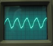
you guys were right on the money, check this out.
850kHz oscillation, 2.5V (!!!) peak-to-peak. ugh. 🙁
time to stick the source resistors back in i guess. any other tips for getting stability out of this circuit? maybe decrease the open-loop gain by adjusting the top resistor? hmm, is there somewhere i could stick a compensation cap?
Attachments
compensation
Shooting from the hip,
I think that 850 kHz is too low a frequency to be related to not having the gate resistors in, but you may want to add them anyway.
One place for a comp cap is across the 500 Ohm drain resistor. Maybe you could try values in the range of 1 nF.
Like I said, I'm shooting from the hip. I'll try to think about it more later.
What do you suppose the cable capacitance actually is? 50 to 100 pF?
What about the AC input impedance of the amp? Often the amp will have a high DC input impedance in parallel with a low pass filter that might be a 1 kOhm resistor +several nF capacitance.
The compensation idea I mentioned might do more harm than good; a 1 nF would add a 320 kHz pole to the system. Maybe the cap has to be much bigger, but if it is much lower then you get into phase issues in the audio band. It depends on where the problem is arising. So consider it well before proceeding. Maybe you will have to put a R on the order of tens of Ohms in series with the C.
Just ideas.
I don't remember, do you have a simulator to play with?
-- mirlo
- Status
- Not open for further replies.
- Home
- Amplifiers
- Solid State
- Son of Dork: Active Circuitry