hey hey let's not get too off-topic...
all the other folks are gonna lose interest if we just post pictures of harry all day long. no offense harry.
all the other folks are gonna lose interest if we just post pictures of harry all day long. no offense harry.
I can't see any details, picture is too dark
Yep....... Like I would dare show my face on this forum. There are people from Texas on this forum. My life wouldn't be worth a plugged nickle. Next thing someone will want my phone number....
H.H.(Happily Hidden)
Yep....... Like I would dare show my face on this forum. There are people from Texas on this forum. My life wouldn't be worth a plugged nickle. Next thing someone will want my phone number....
H.H.(Happily Hidden)
cable chargers?
i vaguely remember a while back, there was a product called a "cable charger" which DC-biased interconnects on one end, and AC-coupled them at the other with a high-quality film cap. supposedly this was supposed to optimize the signal transmission to some degree, though it was never explained to me how it did so. the editor of my audio magazine said despite the added coloration of the capacitor, he felt it often made a worthwhile improvement in sound quality.
i was just thinking about this in connection with my "Son of Dork" preamp... just random thoughts of the Borbely SE circuit, high-pass filtering my main speakers (i have a subwoofer), connecting the preamp to my amp, and dielectric performance. it occured to me that all cables are capacitors to some degree, and most any capacitor seems to perform better when DC biased so as to avoid signal zero-crossing. maybe this "cable charging" stabilizes the dielectric and avoids any nasties that might be associated with zero crossing? there was also some claimed supression of RF interference, though i have no idea how that would work.
so i have an idea for Son of Dork... why not combine the best of every world? i could use the Borbely SE circuit, which has an output offset somewhere around +12V or +15V depending on supply. then, i would have a special DC-coupled output on the preamp that has no coupling cap - just the straight SE output, DC bias and all. i would run this signal through the interconnect to the amplifier, then have in-line RCA/XLR adapters at the amplifier end with blocking caps in them. i could even select the value of the cap to deliberately high-pass filter the signal where desired, say at 60Hz for my main speakers.
using such a scheme, i could use a SE preamp circuit that everyone seems to favor, get the benefits of cable DC biasing, optionally high-pass filter my mains, and still have only one capacitor total in the signal path. the only catch is that i'll have to be VERY careful to label the DC-coupled output of the amp as such, and only use this output in conjunction with the blocking caps at the other end - otherwise i could fry my speakers in an instant. i might consider even using a different type of terminal/cable (BNC or something) to prevent such an accident.
thoughts?
dorkus
Simple 2 stages with attenuator in between?
Please find attached a simple preamp circuit. It is missing trim and detail engineering. I like it for the following reasons:
1. "No" feedback
2. As much or little gain as you want
3. No cascodes
4. No level shifters
5. Room for attenuator between stages which DOES NOT have to go to ground (runs in balanced mode).
6. Fully balanced: converts balanced to single ended and vice versa
7. DC coupled
8. For single ended operation, switching phase is very easy, just choose the other output.
9. This is "basically single ended application" of a balanced circuit. I say this since single ended gain is developed over a single resistor with "single" gain device. Borbely appears quite fond of the other approach, (push-pull) input with complementary JFET's with their gates connected.
Let me just explain briefly what is going on in the output stage. I chose drain output so that voltages can be shifted back to zero without added complexity. The gain of the ouput stage is just over 1, so there is significant degeneration. It can be construed that the output impedance will be very low even given the drain output. Without degeneration, balanced mode output impedance is 616 Ohms as shown. With feedback, it is probably in the region of 200 or so Ohms. Of course an SE output has half that output impedance.
I would argue this is just about as simple as you can make a circuit given a requirement for 2 amplification stages with passive attenuation between them.
What do you think?
Petter
Attachments
Interesting, Petter.
Have you simulated this? With which FETs?
How much do you feel you gain from the second stage being differential also as opposed to a more conventional common source amplifier tied to the rails? (besides higher PSRR). Performance could be quite good without going complementary, but DC balance if you're using it single ended would be a problem. Were you considering output capacitors?
The gain structure is very similar to an FET DAC output buffer I designed, but my circuit is more (too much?) complicated compared with yours, it is complementary, and I used somewhat higher power supply rails and Zetex bipolars for the outputs. It is a NLFB circuit also, and uses some other measures to linearize the first diff amp, which can do single ended to balanced and vice versa; it's designed to work from differential DAC output chip.
I like your concept- hopefully you'll keep us informed of how it develops.
Regards,
Jon
I have not simulated this, but I have built something very similar in my Pearl. I would say that the second stage in my pearl (SE version of the above) with 4 JFETs has fairly similar operating conditions as the above -- except it runs with cascode due to the much higher gain.
Balanced operation of output stage costs very little in terms of components and alows a volume control which does not involve ground. I like the symmetry, and it is easy to guarantee absolute output voltage level by trimming the current source. Current sources in diff amps really are very neat for this purpose, as they handle biasing automatically, as well as output DC level 🙂
No, I did not consider output capacitors. I use the best ones available on the market: No such things. It is true that one could go with n polarity devices all around, but as you state, that means more complicated power supply and/or strategically placed coupling capacitors.
I originally had higher PSU voltage for the bottom side, but decided to reduce it given that I was expecting flames due to higher output impedance this causes. Of course, one could build this like I build my Pearl v2 which is balanced with 8 JFET's per half per stage. Then we could double the low side voltage while keeping the output impedance the same.
Suggested devices: n: 2SK170, p: 2SJ109 or something like that.
Petter
Volume control for above is here
http://www.diyaudio.com/forums/showthread.php?postid=38259#post38259
http://www.diyaudio.com/forums/showthread.php?postid=38259#post38259
Well my Pearl which is basically the same sounds very good. It is not really directly comparable, though.
A pro friend of mine says that he feels that symmetric Borbely type push-pull input has a less "coarse distortion structure" whatever that means.
I would think this type of circuit, especially with the high level of degeneration will be extremely linear even without loop feedback. Incidentally loop feedback is easily implented, but you have to "cross" so that you take output on right to input on left and vice versa given the even number of gain stages.
Noise should also be low since all gain is takein in first stage, and since devices are very low noise + paralled (good enough for an MC RIAA stage).
The circuit works with any gain device. Some may prefer BJT's, tubes or a mix thereof.
Petter
As beeing an amplifier designer.
As beeing an amplifier designer since many years.
I must say your entuiasm is fantastic.
I am no fan of Nelson Pass designs, neither can I understand
the "use (MOS)FETs constructions at any price"-spirit.
In audio low noise bipolar is mostly
the most suitable alternative.
And in the output stage Bipolar have no match!
I have seen at your suggestions. They might work well,
but aren't they a little unnessesary complicated?
Why make things harder than it need to be?
Although no fan of Pass Amps, one of Nelson's
guidelines is "KEEP IT SIMPLE".
There I agree totally.
Often this is the most cost effective way also.
Less money spent.
Short signal path.
Fewer components for signal to pass through,
and thereby be colorated.
Few and good components is the way to go.
This is the best HIFI preamp design I have ever seen.
Give it an eye.
Simple is not the same as bad.
In this case quite the opposite.
http://www.mitedu.freeserve.co.uk/Circuits/Audio/gmpre.htm
Groman from Sweden, Amplifier expert
gromanswe homepage:
http://www.geocities.com/gromanswe/🙂
still alive and kicking
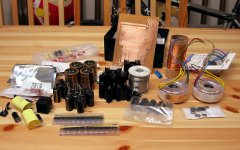
just wanted to let everyone know that SoD is still alive and well. it took me longer than expected to get the parts i needed together (and i still wound up going to Radio Shack for a few things) but i am ready to start prototyping. here are some goodies i've assembled for the first phase of the project... nothing too fancy but some nice Nichicon Muse/Panasonic FC power supply caps, Black Gate coupling caps, Panasonic P polypropylene film bypasses, some leftover Solens, Noble pot, Holco/Yageo/RS carbon film resistors (just for prototyping, Caddocks can come later), the necessary MOSFETS and JFETS, etc. etc. you can also see the power supply circuit board i etched last night, i will post details later on how making that went (i tried regular glossy paper this time instead of "special" toner transfer paper i used in the past).
first up... the Borberly JFET buffer (based on White cathode follower), to be followed by the SE JFET line amp. after i finish the power supply of course (the simple pass regulator design used in BoSoZ).
Attachments
JFET buffer complete
i just finished my Borbely JFET buffer tonight, for a background of the circuit check out this thread:
http://www.diyaudio.com/forums/showthread.php?threadid=2281
my circuit is the same as shown at the bottom, with Harry's last corrections. i've just plugged it into my system and the sound is very promising... can't say it sounds exactly like a straight-wire bypass but it is impressively clean, with great dynamics. i used really cheapo-quality parts too so the circuit is performing nowhere near its potential. more details and pics to follow soon...
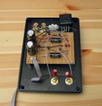
buffer circuit
here's a picture of the (messy) circuit i wired together. as i mentioned earlier, parts quality is pretty ordinary so i am not extracting the "ultimate" potential of this circuit, but just trying to get a feel for its capabilities. the resistors are cheap Yageo (Digikey) and a couple Radio Shack carbon films, except for attenuator series resistor which is a 15k Holco. a Noble 25k pot is used for attenuator shunt. the feedback cap is a .15uF Solen metalized polypropylene, the closest thing i had to the .22uF specified by Borbely. local supply bypassing is a 1000uF Pana FC and .01uF Pana P film.
i did not even bother matching devices (too lazy, and i haven't put together my matching setup yet) so there is 30mV of offset in both channels. the output of the circuit is therefore coupled with a 10uF Black Gate nonpolar, followed by a 100k shunt resistor.
Attachments
buffer sound
the sound of the circuit is quite good... in many respects, very transparent. tonally it is just very slightly bright, but not in a sort of "white light" irritating way, just a slight brightening of the overal tonal shading. i've compared with my passive preamp (just a simple shunt attenuator), and the only drawbacks i've heard thus far are the slightly forward, less relaxed presentation, very slightly less resolution at the very lowest levels, and reduced soundstage depth, which could probably be improved by using a dual mono circuit instead of the sloppy stereo one i put together. interestingly, even though i find it somewhat forward and bright, it still sounds very even and neutral in presentation, and the dynamics are fantastic - definitely an improvement over the purely passive design. what i like best though is the ease with which leading edges and impulses come across, giving the sound a crisper, more defined character... probably because it is relieving the upstream source (cd/sacd player) of load. the buffer's dynamic characteristics seem much better than that of opamps i've heard, transients come across extremely crisply and convincingly, no overhang or ringing. triangles and cymbals sound very clear, maybe just a tad hashed compared to passive pre but crisper. bass is also excellent, so far i have not noticed any aberration despite the capacitor coupling, and the lower midrange down is slightly fuller and more powerful. i have the slight sensation that micro details are somewhat obscured compared to the passive (after all no active circuitry is the best), but at the same time i don't feel i'm losing much detail. instrumental timbres are a strong point as well, oboe timbre is dead-on. oh yeah, and it is absolutely dead quiet - not a trace of hiss or hum.
if it were a little smoother-sounding and did not reduce soundstage depth, it would be near perfect. i think many of these characteristics could be improved with better parts. the Solen coupling cap i used tends to be a little bright and flat i think, so using, say, a good Hovland there would improve matters greatly methinks. nice resistors (Caddocks, Vishays?) would improve matters further. in short, this little circuit sounds great, and has much potential with better layout and parts.
oh, i forgot to mention, you can find the power supply i used here:
http://www.diyaudio.com/forums/showthread.php?threadid=3627&pagenumber=4
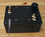
here's a picture of the box the circuit is in, just a plastic Radio Shack project enclosure.
the sound of the circuit is quite good... in many respects, very transparent. tonally it is just very slightly bright, but not in a sort of "white light" irritating way, just a slight brightening of the overal tonal shading. i've compared with my passive preamp (just a simple shunt attenuator), and the only drawbacks i've heard thus far are the slightly forward, less relaxed presentation, very slightly less resolution at the very lowest levels, and reduced soundstage depth, which could probably be improved by using a dual mono circuit instead of the sloppy stereo one i put together. interestingly, even though i find it somewhat forward and bright, it still sounds very even and neutral in presentation, and the dynamics are fantastic - definitely an improvement over the purely passive design. what i like best though is the ease with which leading edges and impulses come across, giving the sound a crisper, more defined character... probably because it is relieving the upstream source (cd/sacd player) of load. the buffer's dynamic characteristics seem much better than that of opamps i've heard, transients come across extremely crisply and convincingly, no overhang or ringing. triangles and cymbals sound very clear, maybe just a tad hashed compared to passive pre but crisper. bass is also excellent, so far i have not noticed any aberration despite the capacitor coupling, and the lower midrange down is slightly fuller and more powerful. i have the slight sensation that micro details are somewhat obscured compared to the passive (after all no active circuitry is the best), but at the same time i don't feel i'm losing much detail. instrumental timbres are a strong point as well, oboe timbre is dead-on. oh yeah, and it is absolutely dead quiet - not a trace of hiss or hum.
if it were a little smoother-sounding and did not reduce soundstage depth, it would be near perfect. i think many of these characteristics could be improved with better parts. the Solen coupling cap i used tends to be a little bright and flat i think, so using, say, a good Hovland there would improve matters greatly methinks. nice resistors (Caddocks, Vishays?) would improve matters further. in short, this little circuit sounds great, and has much potential with better layout and parts.
oh, i forgot to mention, you can find the power supply i used here:
http://www.diyaudio.com/forums/showthread.php?threadid=3627&pagenumber=4
here's a picture of the box the circuit is in, just a plastic Radio Shack project enclosure.
Attachments
black gates
i'm not sure how to describe the "sound" of the BG caps, as i haven't done a formal comparson w/a straight bypass, but i have used them in a couple circuits and here is what i've found: compared to other electrolytics, they are far more transparent, but they do not sound like films either. i think the sound is robust, and definitely on the fuller side compared to films. in general i think 'lytics as coupling caps tend to be less thin and bright compared to (most) films, but their problem is usually muddiness and lack of definition. the resolution of BG's is excellent, but they give up perhaps just a bit of HF resolution to the films for a smoother, warmer sound; they sound slightly "massaged" compared to films, but i would hesitate to call them blatantly colored... all caps are, but the BG's keep up with good films overall. i think they are very worthy coupling caps, and i am not even operating them with a proper DC bias.
in the JFET buffer circuit, i currently have a .15uF Solen for the feedback cap, and it is biased 20V or so. perhaps i will experiment with Hovland film and BG caps here to see how they compare.
Capacitors
What capacitors are you talking about?
Input and output caps? They are not in the circuit then.
You mention a 150n Solen, but the one on the diagram is 220n. Did I miss something?
Is there a way to use this circuit and get away without input/output caps? It seems there is not, except if you add a servo.
Carlos
Input and output caps? They are not in the circuit then.
HA HA HA HA HA HA HA HA HA HA HA HA HA HA HA HA HA HA HA HA
HA HA HA HA HA HA HA HA HA HA HA HA HA HA HA HA HA HA HA HA !
HA HA HA HA HA HA HA HA HA HA HA HA HA HA HA HA HA HA HA HA
HA HA HA HA HA HA HA HA HA HA HA HA HA HA HA HA HA HA HA HA !
Black Gates are actually sitting on output jacks, because Dorkus didn't match FETs and got 30mV of DC offset. When you match, you should be OK with output and no caps are needed. Solens are in a feedback. I don't think it matters if it's 150 or 220nF. BTW it might be not possible to obtain such small value from BG.
ok harry, i gotta admit i am laughing w/you on that one... 😛
the value of the feedback cap is not critical, i'm not sure what kind of impedance it's seeing but i'm guessing it's pretty high and even with .15uF the LF cutoff is probably pretty darn low. Black Gates actually come as low as 0.1uF, but i would probalby use larger values and put them in series to get more voltage out of them, according to my sim it is at least 40V across that capacitor but i haven't verified in-circuit yet...
yeah Peter (what happened to HPotter?), you can definitely get offset negligible with proper matching, however there is still the risk of some drift. i know we hate servos but i was wondering if i could build one into the -24V rail, to vary the negative rail slightly to keep DC balance. i could keep the simple pass-transistor regulator i'm using but instead of feeding the gate of the MOSFET w/voltage references i would use an opamp or something to vary it according to offset. does that sound like a really bad idea?
- Status
- Not open for further replies.
- Home
- Amplifiers
- Solid State
- Son of Dork: Active Circuitry