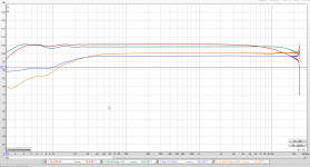
Hi trobbins, post #58 , The sweep output from PC goes into the amplifier , and what I measure (send back into the PC) is the voltage over the 1K of the 100k/1K attenuator.
The freq response can be improved as schematic attached, change in NFB loop. Bottom end response can be adjusted with screen bypass cap.
Thx Koonw, will experiment with this too
Sorry to bug you but can you confirm the 'input calibrated' trace that is a flat-line response in your measurement plot, is when the PC sweep output is directly connected to the top of the 100k:1k divider (as per a typical loopback test of baseline frequency response)?Hi trobbins, post #58 , The sweep output from PC goes into the amplifier , and what I measure (send back into the PC) is the voltage over the 1K of the 100k/1K attenuator.
Kevin I was just going to measure the frequency response,my above feedback was based on power output at 4 Ohm. Stumbled a ghost / crosstalk phenomenon. (I always tested with one channel connected only now all tubes are in and 2nd speaker connected)
As soon as I connect the feedback input the dormant channel with no input starts to become active / provide sound at reasonable volume (music or measurement sweep)
Disconnect the input into PC loop again and it stops ... , actually starts stops as soon as I connect the GND.
But that channel has no input connected ...
Ghost in the machine ...
I mentioned early on in this thread that I had had a similar issue with sound quality, and that I noticed crosstalk as well. I had one wire swapped between the OPTs and the channels. I am sure you have double-checked every potential connection (including the feedback connections) but if you have crosstalk then you must have a connection error somewhere.
Hi OldHEctor yes I noticed your comment, although in my design it is hard to not connect correctly, now I only have the crosstalk in my measurement setup (so must be something there with gnd loops or s o ...) do not have it in audio. Still was wondering the same I will re-check.
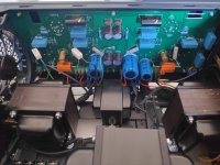
Notes, the connections picture is what I got from the vendor but I traced the paths and looks ok , messy connections on the amp picture is since I'm still testing 🙂 , I replaced all capacitors with good (new) ones some that where on where second hand / re-used
FYI board is double sided.
Notes, the connections picture is what I got from the vendor but I traced the paths and looks ok , messy connections on the amp picture is since I'm still testing 🙂 , I replaced all capacitors with good (new) ones some that where on where second hand / re-used
FYI board is double sided.
Attachments

Last edited:
Sorry to bug you but can you confirm the 'input calibrated' trace that is a flat-line response in your measurement plot, is when the PC sweep output is directly connected to the top of the 100k:1k divider (as per a typical loopback test of baseline frequency response)?
Without remeasuring I can already say no - the flat line response is the input and output from my Behringer UCA222 directly connected. (the measurement primary loop)
Then I unplug the RCAs , put the amp and load device in between and send the measurement over the 1K of the 100k:1k divider back to input of UCA222 .
Notes, the connections picture is what I got from the vendor ...
I noticed you have connections for 'output cattle'. Do you have high moo tubes?
😛 Yes funny noticed that (t) mooo.... but these cattles do not give milk as they are supposed to do ...
ps The vendor called them that way, just making sure I still have a little credibility here 🙂
ps The vendor called them that way, just making sure I still have a little credibility here 🙂
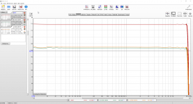
A big step closer with success, I tested with an universal Hammond 125 E and EL34s in Pentode, Transformer (Rated 15W 80 mA / 15 Khz) and immediate with or without feedback a full 20 Khz response 😀 disregarding the poor low, it is just a small test transformer.
Music was immediate fresh, I knew I missed something 🙂
So I looked at the suggestion of Kevinkr for Monolith Magnetics, very friendly and helpful people but unfortunately they are about 4 times as expensive as the Hammonds (but super specs) , it would be out of proportion for the other components in this build. But for sure next one they will be on the list.
So tested with the 125E gave me good confidence and I ordered the Hammonds they are rated, Frequency response 30 Hz. to 30 Khz. at full rated power (+/- 1 db max. - ref. 1 Khz) minimum 60 Watt.
Will then decide if I go Pentode or UL.
Fingers crossed ! Again thx for all the help and valuable insights.
Attachments
Last edited:
measure your frequency response at the plates of the input tube and splitter.
you can remove the splitter tube and measure it there. the input is high gain and may limit the bandwidth.
you can remove the splitter tube and measure it there. the input is high gain and may limit the bandwidth.
The freq response can be improved as schematic attached, change in NFB loop. Bottom end response can be adjusted with screen bypass cap.
Hi Koonw, can you share the spice file please ? 🙂
What is it ? What application is using this ?
It the simulation file KoonW has made for Kspice
Brgds,
Ives
Happy here, I've put the new output transformers in and immediately all good 🙂
Thx for all the helpful feedback.
At present I can only measure till 20 Khz (new 24 bit / 192 Khz audio card is ordered) but I can hear the significant difference and no drop on the graph till 20 Khz and beyond. All good.
It plays really nice and more than sufficient power but maybe a final theorethocal question? Do I understand it correct that I do not get the full power potential (shall I start a new thread ?)
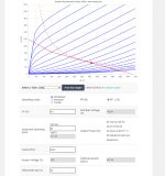
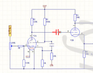
It's cathode biased and voltage over cathode resistor is ~39v so the control grid is virtually more negative than the cathode. Just before clipping of the 6U8 phase splitter output I have around maximum 34 Vpp input on the KT88 control grid (+- 17 V) For full power output would it not require (theoretical) a +-40 V (80 Vpp) on the control grid input of the KT88s ?
Looking forward to be educated 😉
Thx for all the helpful feedback.
At present I can only measure till 20 Khz (new 24 bit / 192 Khz audio card is ordered) but I can hear the significant difference and no drop on the graph till 20 Khz and beyond. All good.
It plays really nice and more than sufficient power but maybe a final theorethocal question? Do I understand it correct that I do not get the full power potential (shall I start a new thread ?)
It's cathode biased and voltage over cathode resistor is ~39v so the control grid is virtually more negative than the cathode. Just before clipping of the 6U8 phase splitter output I have around maximum 34 Vpp input on the KT88 control grid (+- 17 V) For full power output would it not require (theoretical) a +-40 V (80 Vpp) on the control grid input of the KT88s ?
Looking forward to be educated 😉
Attachments
Your phase splitter is a cathodyne direct coupled to the first stage? If so, it may be that the first stage anode voltage (= grid voltage of the 6U8) is higher than you want. This reduces the voltage across the 6U8 and can limit headroom. Ideally you should have 80-90 V on the first stage anode (no more than ~110V if you want to achieve the full swing required). These numbers are guesstimates and could be out a fair bit 🙂
Hello Tikiroo, apologies the diagram I got from the vendor is not entirely correct, there is a coupling capacitor between the pentode and triode. But the voltage on the first stage anode is definitely much higher than 110V. But I assume with the coupling capacitor that does not matter ?
Attachments
- Home
- Amplifiers
- Tubes / Valves
- Some help please - Tube amp Poor frequency response