Have you tried the other speaker tap? If you have 8 ohm speakers, it could be that they are closer to 6 ohm, and the impedance varies over the whole bandwidth anyway. For the best sound I use my Tubelab SSE on the 4ohm setting with my reasonable quality bookshelf speakers.
Can I suggest you confirm the frequency response at the EL34 grids (across the 330K leaks), and that there is low distortion, at the signal levels you are using to indicate the amp output has poor HF response - so that we know the input and PI stages are 'blameless'. And similarly, confirm that the distortion on your output test load resistor is consistent (ie. the output stage is not being asked to do anything more than simple class A - if you operate in to class B then the effective shunt capacitance presented by the OT primary doubles, reducing your OT's frequency response).
It could also be just simply that you are operating pentode mode, where the effective source impedance of the EL34 anodes are about 10x the level of if you ran in triode mode. The OT is also presenting 5kPP, which is quite low compared to the effective anode impedance, and so the final OT response is likely to be quite poor. You would have to go through Lee's transformer response guideline to ball-park how poor, and also try and measure the lumped capacitance of the OT primary, and its first resonance frequency. This is a key reason why the Williamson amp ran triode mode, and with a 10kPP OT.
It could also be just simply that you are operating pentode mode, where the effective source impedance of the EL34 anodes are about 10x the level of if you ran in triode mode. The OT is also presenting 5kPP, which is quite low compared to the effective anode impedance, and so the final OT response is likely to be quite poor. You would have to go through Lee's transformer response guideline to ball-park how poor, and also try and measure the lumped capacitance of the OT primary, and its first resonance frequency. This is a key reason why the Williamson amp ran triode mode, and with a 10kPP OT.
Table 4 on page 7 of this AES paper by Menno van der Veen seems to show different results. Two EL34's in push-pull, using the same OPT with 4K impedance, give better high frequency response in pentode mode (- 3dB at 47 kHz) than in triode mode (- 3dB at 24 kHz).
https://mennovanderveen.nl/cms/images/onderzoek-ontwikkeling/publicaties/download_3.pdf
https://mennovanderveen.nl/cms/images/onderzoek-ontwikkeling/publicaties/download_3.pdf
The diagram you posted has no ground connection on the transformer secondary. Is this how you have wired it up?
Reading through this thread, and I cant help but wonder...
Is the OPT just too small? Core size of 35x45mm seems small for the power. Sounds like a 20VA lam size to me, and I'm no expert but, my little 2 W amplifier uses a core that would find a home in a 100VA transformer.
May be something, may be nothing.
Is the OPT just too small? Core size of 35x45mm seems small for the power. Sounds like a 20VA lam size to me, and I'm no expert but, my little 2 W amplifier uses a core that would find a home in a 100VA transformer.
May be something, may be nothing.
trobbins, other helpful friends, yes I connected the OT to ground. The board only came with this principle diagram. something that confuses me a bit in the answers is that triode, pentode are used in the namings. The board states it can handle both EL34s or KT88s (with adjusted cathode bias resistor) and is default in triode mode the screen connected to the 1K to B+. I have now connected (for testing ) the screen grid to the UL OT tabs. But KT88s are tetrodes, so I'm wondering how do you match an EL34 pentode in the connections. (I did not change anything on the board) , going to read a bit what happens to the 2nd screen grid of an EL34 normally. (is that just a not connected pin on the KT88 ? / or connected to the same pin on an EL34 ?) But all feedback welcome.
KT88 and EL34 has identical socket connections except for pin 1
EL34 has pin 1 connected to the g3 and an amp using EL34 should have
pin1 and 8 connected together.
KT88 has g3/beam former internally connected to the cathode ( pin 8 ). Pin1 is not connected.
EL34 has pin 1 connected to the g3 and an amp using EL34 should have
pin1 and 8 connected together.
KT88 has g3/beam former internally connected to the cathode ( pin 8 ). Pin1 is not connected.
PeterTub, Prairieboy, KevinKr and all of you thank you for the feedback, I'm back from holiday and I have redone the measurements without the negative feedback connected and it is bad. I am using the output transformers that Prairieboy linked. Without neg feedback I have 82% less output on 20 KHz than on 400 Hz . I triple checked every measurement. (See attachment) All is reasonable up to the KT88's grids but at the output of the opt's or even the PLATE-PATE voltage drops dramatically. (something I did not expect) B+ stays stable.
I cannot say I fully understand why the plate to plate voltage drops. I would think higher frequency is higher transformer resistance and less load on the tubes. But maybe the tubes internal resistance increases or the secondary wingdings give more load ..or ..or ? For the moment I'm thinking of ordering another transformer (Hammond) and I'm reading about load-lines to determine if I need the 4Ks/5Ks(as now) /6.3Ks. I'm looking at this load-line calculator Loadline calculator for power stages with reactive load - Vacuum Tube Amplifiers - DIY but I'm not sure were the operating point should be, I see the power increasing but there must be more than that like THD and impact on frequency response ? ...
Still any input on the original problem above, the drop in plate to plate voltage is greatly appreciated. I'm a bit lost ...
Attachments

As you live in europe a european supplier might be beneficial.
This one is in UK ( still within EU )
Push-Pull Output Transformers – Primary Windings
This one is in UK ( still within EU )
Push-Pull Output Transformers – Primary Windings
My suspicion would be excessive distributed capacitance in the primary windings if you have the screen grids connected to B+ (aka pentode connection).
If you reconnect the output tubes as triodes (screen grid to plate through 100 ohm resistor) the HF response will improve if it was due to winding capacitance.
I recommend replacing the transformers with something better from Europe. Options could included Sowter, Trafomatic or Monolith Magnetics depending on budget. There are good transformer makers in Germany as well, but I am not aware of who they might be.
Also I (only ?) get 15.9 Watt RMS (11.3 V RMS) before clipping on the 8 Ohm terminal with an 50W8R resistor, this seems low compared to some other KT88 UL projects I have seen and/or calculators. When the 8 Ohm output (just not) clips the Plate2Plate voltage on the OPT is 288 Volt RMS (814 Vpp) seems ok since the B+ is 410 Volt, does this seems ok in your experience ? Both measurements are at 400 Hz (This is what my meter can do in RMS) and cross checked with scope and calculated RMS values.
Apologies for all the questions, all feedback is truly appreciated.
Apologies for all the questions, all feedback is truly appreciated.
If you have low/er/ budget, the Toroidy PP transformers also acceptable.
Push-pull - Shop Toroidy.pl
TME also sells Toroidy transformers:
TTG-KT88PP TOROIDY - Transformer: speaker | 80VA; O115x65mm; 0.012/56kHz; 300mA | TME - Electronic components
Push-pull - Shop Toroidy.pl
TME also sells Toroidy transformers:
TTG-KT88PP TOROIDY - Transformer: speaker | 80VA; O115x65mm; 0.012/56kHz; 300mA | TME - Electronic components
Hi Kevinkr originally the screens were connected (how the board came) via a 1K/5W to the B+ (Triode mode) I did not test with them directly to the B+ for pentode , I do have the screens now connected to the UL tabs on the OPT , any precautions I need to do / other changes required for connecting them to the b+ ? (besides do not touch 🙂 ) , just making sure.
Hi Euro 21 yes I was already looking at them.Just held back by 2 things the Toroidal model then I need to rebuild the case (but acceptable) but also in the study from mennovanderveen Home he mentions that cathode based biasing is not good for Toroidal transformers due to the potential difference in bias currents and early saturation. But they are for sure on the list.
ps, I do not mind investing in the correct transformers but also careful not to just throw money away 🙂
Thx Guys
IvesH, can you clarify your post #29 results please. Are all those voltage measurements a pk-pk level (as you refer to them as 'tt')? Are they measured by your scope? How have you set up your probes and scope to measure KT88 plate-to-plate voltage? Is your speaker secondary grounded (as the schematic in post #1 doesn't show that)? Are the KT88's connected in triode or pentode or UL mode?
Are your measurements taken when operation is sufficiently within class A (ie. sufficiently below clipping with only minor rise in distortion)?
Maybe if you include your setup conditions in with your results in an attachment then that would be less ambiguous.
Are your measurements taken when operation is sufficiently within class A (ie. sufficiently below clipping with only minor rise in distortion)?
Maybe if you include your setup conditions in with your results in an attachment then that would be less ambiguous.
Hi Kevinkr originally the screens were connected (how the board came) via a 1K/5W to the B+ (Triode mode) <snip>
Hi Ives, just to clear up some minor confusion on your part, the connection you refer to as "triode" is in fact pentode connection. For triode mode the screens are connected to the plates of their respective output tube. (I typically use a 100 ohm resistor between pins 3 and 4 of each output tube.)
Did you cut the etch between pins 4 of the output tubes on the original board when you connected in UL mode? The pentode mode connection shows the screens both tied to that single 1K/5W resistor to B+.
Currently you have tried pentode mode, if pin 4 of both output tubes are connected together still then connecting the UL taps to the screens has shorted part of the output transformer. I'd not expect it to work in that scenario, so have you separated pin 4 on each output tube from the original PCB trace by cutting it?
You have not tried triode mode at all to the best of my ability to understand what you are doing. 😀
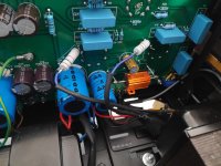
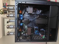
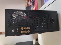
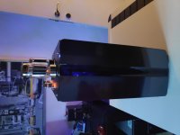
Can you post some pictures of how things are arranged.
Hi Trobbins, Yes I use tt (top/top) as pk-pk, I measured across the ot / plates with a normal probe set to 1/10th and with a RMS multimeter at 400 Hz , same result. Yes secondary is grounded. At present the screens /g2/ pin 4 are connected to the UL connection of the OT (via the 1K resistor that was connected to B+) I just disconnected the hot B+ side from the 1K and connected that to the UL connections. Also tried a direct connect from the UL connection to the screen/g2 pin 4. This gave the same frequency response.
Hi Kevinkr, you are correct I have not tried triode mode, will do that tonight. Pin 4 of the output tubes are not connected together, each of them has/had a separate 1K to B+ (picture attached) , now connected to the UL OT connections.
ps1, attached pictures, this is for testing , will clean up the board, appropriate resistors and connections later.
ps2, Pin 1 and 8 are not connected together seems conflicting with the earlier comment from petertub since the board states EL34/KT88, anyhow focussing on the KT88 for now.
Attachments
Just refocussion on a previous comment I only get 15.9 watt RMS while this loadline calculator gives much more for my values. Loadline calculator for power stages with reactive load - Vacuum Tube Amplifiers - DIY , just sharing might be important (not really interested in a lot of power but might be a symptom). I'm ready to order the Hammond 1650NA OTs (I can get these locally) http://www.hammondmfg.com/pdf/EDB1650NA.pdf
Hi Ives,
Given that you are located in Belgium I strongly recommend you talk to Ward or Yves at Monolith Magnetics before purchasing the Hammonds to make sure you can't get something from them for not too much more. (With duty and freight costs you may be in range of something much better than the Hammond)
I actually get all of my audio transformers from them, and yes they are expensive, but in the case of transformers you get what you pay for. I think they are worth the money in spite of the shipping cost and import duty.
I'm not affiliated in any way, but as a former resident of Brussels I have a soft spot for Belgium in general.
Welcome to MONOLITH MAGNETICS | MONOLITH MAGNETICS
- Home
- Amplifiers
- Tubes / Valves
- Some help please - Tube amp Poor frequency response