True, will measure later, sorry they are on the board will post the values and adapt the schematics. Thx
Is my principle assumption correct ?
It's cathode biased and voltage over cathode resistor is ~39v so the control grid is virtually more negative than the cathode. Just before clipping of the 6U8 phase splitter output I have around maximum 34 Vpp input on the KT88 control grid (+- 17 V)
For full power output would it not require (theoretical) a +-40 V (80 Vpp) on the control grid input of the KT88s ?
If there is a cap as shown in red there MUST be a grid resistor too.Hello Tikiroo, apologies the diagram I got from the vendor is not entirely correct, there is a coupling capacitor between the pentode and triode. But the voltage on the first stage anode is definitely much higher than 110V. But I assume with the coupling capacitor that does not matter ?
It might be more then one error, it might be better to recalculate the whole stage.
What is the actual schematics right now, and what is the important voltages ?
For full power output would it not require (theoretical) a +-40 V (80 Vpp) on the control grid input of the KT88s ?
Yes
So we arrived at post # 80 to find out that the schematic you presented doesn't reflect your build. Are there more differences?
The lesson of this thread is to avoid Chinese transformers (and most of their other audio products and kits).
PS beware of the the UK company linked to earlier - Primary Windings. It contravenes EU regulations because there is no address, no phone number and no email address. The website doesn't have SSL (padlock symbol) and so its insecure.
PS beware of the the UK company linked to earlier - Primary Windings. It contravenes EU regulations because there is no address, no phone number and no email address. The website doesn't have SSL (padlock symbol) and so its insecure.
Last edited:
Yes apologies I missed that since I was focusing on the output OPT stage and Pentode or UL mode. I agree, lesson learned. For now I'll enjoy the amplifier a bit and in a few weeks look if the driver stage can be strengthened (although not needed in my environment).
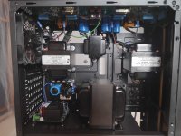
This is the only change I have on the board stage 1 and 2 coupled with a capacitor and the required bias resistors. When I dismantle I'll reverse engineer the board to see if there is anything else missing in the diagram.
(It double sided so I need to fully dismantle) . Will probably do it in LTSpice first.
That said I did find this thread really useful and educational for the frequency problem. Just wanted confirmation a final temporary closure that the swing would need to be increased to drive the output tubes for full output power.
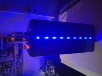
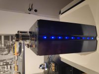
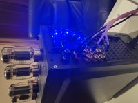
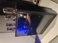
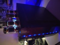
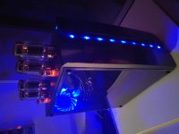
For fun shared the final result.
Thx again for all the help,
Ives
This is the only change I have on the board stage 1 and 2 coupled with a capacitor and the required bias resistors. When I dismantle I'll reverse engineer the board to see if there is anything else missing in the diagram.
(It double sided so I need to fully dismantle) . Will probably do it in LTSpice first.
That said I did find this thread really useful and educational for the frequency problem. Just wanted confirmation a final temporary closure that the swing would need to be increased to drive the output tubes for full output power.
For fun shared the final result.
Thx again for all the help,
Ives
Attachments
-
 IMG_20201001_173657.jpg652 KB · Views: 123
 -
 IMG_20201001_221316.jpg540.5 KB · Views: 130
 -
 IMG_20201001_221608.jpg402.2 KB · Views: 125
 -
 IMG_20201001_225045.jpg410.5 KB · Views: 118
 -
 IMG_20201001_225443_1.jpg483.9 KB · Views: 121
 -
 IMG_20201001_225454.jpg433.1 KB · Views: 55
 -
 IMG_20201001_225514_1.jpg452.3 KB · Views: 64
 -
 IMG_20201001_225529_1.jpg438.7 KB · Views: 60
Ok here it is.
Hello Koonw, I have started to rebuild the amplifier, would you mind sharing the ltspice 6uAp/T, EL34 and output transformer lib models ?
Than you very much !
Table 4 on page 7 of this AES paper by Menno van der Veen seems to show different results. Two EL34's in push-pull, using the same OPT with 4K impedance, give better high frequency response in pentode mode (- 3dB at 47 kHz) than in triode mode (- 3dB at 24 kHz).
https://mennovanderveen.nl/cms/images/onderzoek-ontwikkeling/publicaties/download_3.pdf
The bandwidth gets shifted down with lower generator source impedance (triode) and up with higher source impedance (pentode). Ultralinear is in between. At the high frequency end the impact of the leakage inductance is lowest when "current" fed (pentode). At the low frequency side the impact of the shunt inductance is lowest when "voltage" fed (triode). You cannot make, or use a OPT optimal without paying attention to the source impedance driving it.
Last edited:
I think it is a bit more complicated than that for the high frequency end, where the classical roll-off response of the output transformer depends on a combination of the source resistance and the OT impedance, and that combination can reduce HF response for higher or lower source resistance - it depends on the combination (Lee 1957 shows such an analysis). I haven't looked at the AES paper, but it could be that the pentode source resistance allowed the best response, and any shift away from that would lower the HF response.
At the LF end, the roll off frequency increases with increasing source resistance, but there are a lot of operating influences that move the roll-off corner frequency around (especially signal level which influences primary winding inductance).
At the LF end, the roll off frequency increases with increasing source resistance, but there are a lot of operating influences that move the roll-off corner frequency around (especially signal level which influences primary winding inductance).
Last edited:
Offcourse the -3db hf corner frequency will be influenced by damping of the resonant behaving.
One would try to arrive somewhere between bessel and butterworth.
To get there you have either know manufacturing details of the OT or investigate and take measurements on your own.
With a given OT there is not much to jiggle with, except for the source impedance and,to a lesser extend, load impedance.
If a OT driven with a comparable high source impedance gives you a low -3db hf cutoff you could be in the valley below a peak due to underdamping.
Or, not likely, the early hf fall off is do to overdamping.
The pentode allows best hf response because you get away with higher leakage inductance and this allows winding a transformer with lower capacitance and/or higher shunt inductance.
Feeding a higher L shunt at lf and a lower C at hf both demand less current and produce less tube distortion.
So, with pentodes, given a certain primary load impedance Bw can be wider.
This comes at a cost at the lf end, where the highly distorted magnetizing current do to high source impedance translates into high voltage distortion.
The published -3db lf corner frequency of OTs can be misleading because it is mostly measured under signal conditions that are optimally chosen to give the best looking results.
Last edited:
- Home
- Amplifiers
- Tubes / Valves
- Some help please - Tube amp Poor frequency response