Thx Kevinkr , yes when I build stuff besides being as good as it can be I also want it to look good 😀
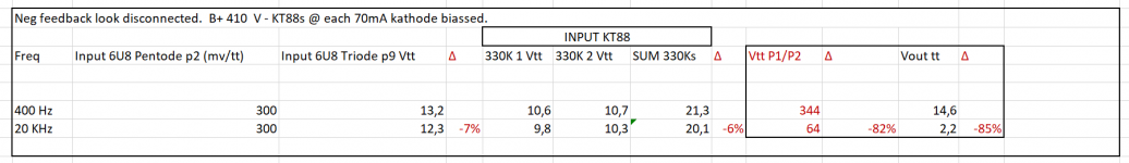
Guys, I have redone and attached the final measurements, also in triode mode before I go output transformer hunting.
Do these values seem normal to you, now not specifically the Freq response (@ 20 Khz) but the produced output power.
It seems the original pentode configuration is the best trade-off between output power and linearity and at low output the (transformer ?) linearity (as expected) is better
Final thoughts ? Again thanks for the feedback, I learned a lot
Attachments

A few people have proposed equivalent circuits for the output stage as a way to assess and appreciate the complicated high frequency roll-off characteristic.
One equivalent circuit representation for class A includes a signal voltage source driving through twice the "plate resistance" of the KT88, in to effectively the primary winding shunt capacitance in parallel with the output reflected impedance (ie. 5kohm PP). The parasitic primary winding resistance can be shown as being in series with the plate resistance, as can primary leakage inductance. In this equivalent representation, the initial roll off can be initially related to the RC filter comprising the plate plus winding resistances, and the winding shunt capacitance (assuming the leakage inductance is low enough to be negligible).
This effect is likely the reason why your measured levels in post #29 show the KT88 plate voltage response mirrors your speaker output response as far as HF drop-off.
Operation in pentode mode would present about a 20x higher plate resistance than in triode mode. So I suggest initially doing a triode mode test of HF response to confirm that, to the first order, that is one of your limiting issues. Yes, you may get a better HF response with another transformer as it may have a lower primary shunt capacitance. I haven't come across sufficient references to summarise the effect of UL operation. The KT88 datasheet indicates ra is 12k for pentode and 670 for triode, at an operating level that may not match yours, but is likely indicative. The low KT ra level for triode mode indicates it may be compromised if the OT primary winding resistance is significant (as the winding resistance adds to ra to form the RC roll-off).
PS. I just saw you have made new measurements in the previous post.
Last edited:
IvesH, your results from post #41 indicate to me that your 'high volume' measurement is likely causing class AB operation to start softly cutting off one side of the output stage, and that is effectively increasing the shunt capacitance being experienced by the signal passing through the other side, and hence degrading the HF roll-off.
One hassle with making any interpretation is that you have included feedback with that latest result, which imho clouds any outcomes you may want from that measurement comparison.
It looks like there is an error with the red filled cell for triode mode, as it shows 1.94 ??
Also your other red filled cells show different W levels than the result cells. You seem to identify 10-15W max output levels, and seem to confusingly use the same signal input level for all tests?
I have a couple of other thoughts, and that is about the output stage operating point and supply voltage.
I'm assuming you have about 60V across the cathode bias network so your effective plate voltage is about 350V, I'd expect about 500 - 550Vpp to be a reasonable upper limit under such circumstances, it would seem you need more plate voltage. (Removing the rectifier tube which does nothing useful except look pretty and delay the B+ might net you another 30V - 40V which would help..
I assume combined quiescent current is around 120mA - 130mA and the tubes are well matched.
The other thing is how much swing does your driver provide before it runs out of steam?
Finally are you sure that is actually an 8 ohm tap? Try loading with 4 ohms and seem what happens, if you achieve > 10Vrms it's likely a 4 ohm tap.
The performance you describe is very mediocre, but even here most transformers back in the day listed specified bandwidth at 1W out and at full power was specified at +/-3dB and that applied to both ends of the spectrum, it appears yours are (much) worse.
Hi trobbins, I measured under more or less the same conditions, the low volume is 1 V RMS and the "high" volume on 4v RMS (the max I could get out of triode mode, and used that as reference for the pentode and UL comparison) , the maximum power one is what I could squeeze out in that mode at 400 Hz, I will confirm power output in triode mode,
The main concern I have is that you have global negative feedback connected whilst trying to take measurements to characterise the HF response of the output stage.
Good afternoon trobbins, sure I will redo the measurements without the nfb connected, am also planning while looking for good output transformers to just buy one of the Hammonds ) they are somewhat affordable and worth the risk, eager to continue testing and see the difference (or not)
IvesH, I didn't see a current sense resistor with each KT88 in your schematic. Have you confirmed balanced PP idle currents?
Side question while testing late yesterday evening at a certain point the speaker of the channel that I was not testing on gave the same output, though I was hearing ghosts. Absolutely sure I did not send any signal into that channel. Will try to recreate today.
trobbins, no only over the common kathode resistor. I just got this adapter today, will confirm individual bias. Biasadapter Bouwpakket - tonefactory.nl
Hi Kevin, yes the tubes are matched and bias voltage 38.8 v ~ 140 mA combined quiescent current. In the prior measurements I got around 10 Vpp over the 330Ks resistors but will reconfirm if that was at max output.
38.8v/470 is about 82mA which is seriously off the expected values and would at least partially explain both the low power and poor frequency response.
Hi,
This is the bias per tube.
Right Channel Pentode mode Tube 1 67.4 / 67.7 mA = 67.55 Avg
Right Channel Pentode mode Tube 2 69.3 / 69.5 mA = 69.2 Avg
2.3% delta
Left Channel UL Mode Tube 1 69.2 mA
Left Channel UL Mode Tube 2 69.5 / 69.8 mA = 69,65 Avg
< 1% delta
measured across a 1 Ohm / 1% resistor in series with the cathode.
Kevin why are they off ? B+ 410 , Cathode R is 277R (for 2 Tubes)
I used this (and other) calculators. Tube Bias Calc
The 470 R was with EL34s now it is 277R in cathode for KT88s.
Kevin,kr, Trobbings, all helpful hands at max output in UL 11V RMS /15W RMS (32 a 34 Vpp 400 Hz) I have pretty much the same voltages on the driver, the triode output (pin 1 and 8) / KT88s input. 330K/1K
Confirmed 8 Ohm connection is 8 Ohm, on 4 Ohm same power result 15W RMS (Less voltage / more current)
Kevinkr can you reconfirm your opinion around your " seriously off the expected values"
Thx for all the great help and your time.
Confirmed 8 Ohm connection is 8 Ohm, on 4 Ohm same power result 15W RMS (Less voltage / more current)
Kevinkr can you reconfirm your opinion around your " seriously off the expected values"
Thx for all the great help and your time.
Forgot one sentence, I have pretty much the same voltages on the driver, the triode output (pin 1 and 8) / KT88s input. 330K/1K , around 32 a34 Vpp at max output of 32 a 34 Vpp on 8 R
Hi Ives,
If the resistor is 277 ohms then the current should be in the right ballpark, but the schematic I saw was 470 ohms, hence the confusion.
I think you've demonstrated that the transformers are of poor quality. Did you try the 4 ohm load as I suggested on the same tap you made the 8 ohm measurement on? What was the result?
Based on what you have described these must be terrible transformers.
Kevin I was just going to measure the frequency response,my above feedback was based on power output at 4 Ohm. Stumbled a ghost / crosstalk phenomenon. (I always tested with one channel connected only now all tubes are in and 2nd speaker connected)
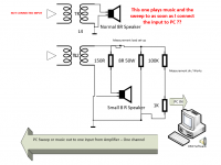
I'm sending in signal (music / sweep) in one channel, OK no problems here
My output load "device" has 8 R/50W resistor , in parallel with 150R with a small speaker and a 30K /1K voltage divider
The divided voltage over the 1K I feeds back to my PC input for the frequency response measurement with REW
As soon as I connect the feedback input the dormant channel with no input starts to become active / provide sound at reasonable volume (music or measurement sweep)
Disconnect the input into PC loop again and it stops ... , actually starts stops as soon as I connect the GND.
But that channel has no input connected ...
Ghost in the machine ...
Attachments
KevinKr, all,
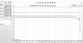
I attached the freq response in combination 4/8 R load over 4/8 R outputs.
I switched my mindset back from focussed measuring crazy mode to relaxed listening, now running in UL mode and it actually does not sound that bad at all. Although we know at full power output / freq it is poor, still going to replace the transformers so I'll give an update here in a few weeks.
In hindsight, I did not pay attention at the time they were cheap (good specs ... but cheap ...) , I mostly build loudspeakers or SS amplifiers ... but I'm sold on tubes. Next one will be with proper neg biassing and all the trims ...
Thx for all the input ! , I'll be back 🙂
Attachments
IvesH, it seems like you have some faultfinding to do wrt the ghost! Eg, pull out V2 on the ghost channel; disconnect the feedback.
Was the calibration test in post #58 a loop-back test of your measurement system with the PC sweep signal connected to the output 100k/1k attenuator to form the test loop?
Was the calibration test in post #58 a loop-back test of your measurement system with the PC sweep signal connected to the output 100k/1k attenuator to form the test loop?
Last edited:
To be honest those sweeps look ok, not brilliant, but ok. I've had similar results before I tweaked a valve amp. Also I'd just use a scope and a sig gen for a quick manual sweep around the frequency concerned. I'd also sweep each individual stage to verify it is the OPT.
If it is the OPT the circuit can be tweaked to give you a bit of HF boost that or tweaked so HF doesn't get rolled off so quick before the driver/ OP stage.
Andy.
If it is the OPT the circuit can be tweaked to give you a bit of HF boost that or tweaked so HF doesn't get rolled off so quick before the driver/ OP stage.
Andy.
- Home
- Amplifiers
- Tubes / Valves
- Some help please - Tube amp Poor frequency response