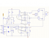
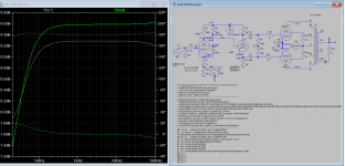
I'm building a KT88/ EL34 CLASS A push-pull tube amplifier with a board I bought online. I attached the schematics below.
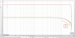
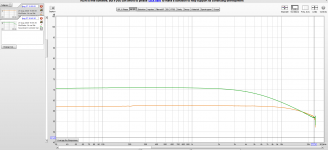
Power enough but the frequency response is poor and drops significantly as from 10 KHz.
The output transformers are supposed to be 5K 60W Push-Pull Ultra Linear, Theoretical Frequency response: 20Hz-25 Khz + -1DB, for KT88 KT100 EL34 6L6 5881.
With KT-88 or EL34 tubes it stays the same (with adjusted BIAS).
I disconnected the negative feedback loop to check if that was causing it but sadly no improvement. For the rest it is a very simple design, so I fear it is caused by the expensive output transformers. Hope you guys (and girls) can suggest or hints to investigate further …
Some specs:
6U8 pentode used as voltage amplifier and triode as differential splitter
360 AC input for B+
B+ 410 Volt (Unloaded 512 Volt)
54UGB Full-Wave Vacuum Rectifier
Separate DC driven 6U8 filaments at 6.26 V DC
KT-88 Tubes biased at 70 mA
From the start replaced all caps with brand new ones.
All resistors measured and good 1 %
Very stable B+
Same result with EL34 tubes.
Any suggestions welcome !
Measurements.png - Google Drive
Power enough but the frequency response is poor and drops significantly as from 10 KHz.
The output transformers are supposed to be 5K 60W Push-Pull Ultra Linear, Theoretical Frequency response: 20Hz-25 Khz + -1DB, for KT88 KT100 EL34 6L6 5881.
With KT-88 or EL34 tubes it stays the same (with adjusted BIAS).
I disconnected the negative feedback loop to check if that was causing it but sadly no improvement. For the rest it is a very simple design, so I fear it is caused by the expensive output transformers. Hope you guys (and girls) can suggest or hints to investigate further …
Some specs:
6U8 pentode used as voltage amplifier and triode as differential splitter
360 AC input for B+
B+ 410 Volt (Unloaded 512 Volt)
54UGB Full-Wave Vacuum Rectifier
Separate DC driven 6U8 filaments at 6.26 V DC
KT-88 Tubes biased at 70 mA
From the start replaced all caps with brand new ones.
All resistors measured and good 1 %
Very stable B+
Same result with EL34 tubes.
Any suggestions welcome !
An externally hosted image should be here but it was not working when we last tested it.
An externally hosted image should be here but it was not working when we last tested it.
Measurements.png - Google Drive
I had a similar issue and discovered I had mixed the coloured wires between the output transformers, so the cause was 'the krank in front of the keyboard' as we used to say in IT support.
Fairly easy to test just by disconnecting inputs one at a time and listening for crosstalk in the speakers.
Fairly easy to test just by disconnecting inputs one at a time and listening for crosstalk in the speakers.
I too had wired the output up inverted once, so the hot went to GND and the gnd-wire from the OPT went to the speaker. When a transformer is hooked up wrong like this, we get the capacitances increased b/c the signal swing in the primary and secondary go opposite and the capacitances get the Miller.
When you disconnected the negative feedback, did the amplifier play a bit louder? If so, than the negative feedback was phased correctly. That means that if you switch the connections of the secondary around, like advised by OldHector, you should also switch the two connections of the primary going to the anodes of the power tubes. If you don't do that, than the negative feedback get's positive. If the board also supports connecting the power tubes ultra-linear, this aslo applies for the two g2 connections coming from your OPT's (if they were connected correctly to begin with).
Last edited:
Attached the images now instead of links.
Thx for all the feedback, seems they are all pointing into the same direction. I'll recheck the connections again. At one time the 2 plate connections where reversed , and the negative feedback became positive and the amp oscillated. Problem is I looked at these already a while and it seems correct based on colouring and info I got from the transformers ... I'll be back 🙂
Thx for all the feedback, seems they are all pointing into the same direction. I'll recheck the connections again. At one time the 2 plate connections where reversed , and the negative feedback became positive and the amp oscillated. Problem is I looked at these already a while and it seems correct based on colouring and info I got from the transformers ... I'll be back 🙂
Attachments
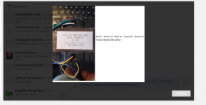
The transformer connections
The transformer connections
So if the anodes / plates are connected correctly on the OT primary side (otherwise I get the oscillation feedback when the negative feedback becomes positive feedback), do the secondary connections still matter. I mean I connected them correctly according to the provided picture but for example, does it matter if the secondary is reversed ? I believe this is what SemperFi suggests ? This is difficult to write 🙂 would the secondary reversal matter ? which one you connect to ground. (of course making sure then the feedback is connected to the correct side not the GND side) ? I'll start experimenting , Thx guys.
Attachments
Last edited:
I think you are right. The amp I had this problem on was a 0NFB type, so I had the OT connected wrong and the only noticeable fault was very poor frequency extension. It sounded very muffled untill I corrected it, and then it was fine.
Attached the images
Are you use soundcard and program (ARTA?) for measuring freq. curve?
Seems the soundcard working at 44.1kHz, so the HF limit of measuring at 22kHz (Red input curve).
The first image HF behaviour not -so- poor, -3dB (green: 102-99dB) at about 22kHz.
Commerce transformer.
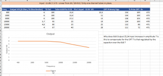
If the measured voltages are correct (good high frequency RMS AC voltmeter -not handheld- ), at 20kHz you measured about -3.5dB, which is different from 1. image freq. curve (-2.5dB).
BTW the schematic shows trioded tubes at PP, but you wrote that transformer bandwidth is 20Hz-25 Khz + -1DB as ultra linear.
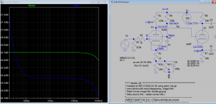
The question in picture 3 "why does 6U8 increase.." that is feedbackAttached the images now instead of links.
Thx for all the feedback, seems they are all pointing into the same direction. I'll recheck the connections again. At one time the 2 plate connections where reversed , and the negative feedback became positive and the amp oscillated. Problem is I looked at these already a while and it seems correct based on colouring and info I got from the transformers ... I'll be back 🙂
trying to compensate what the transformer limits.
Try some other known transformer
Perhaps there isn't enough iron in the output transformer for a good low frequency response. Tell us about the transformer.
Super "feedback "guys, yours not the amp 🙄 , petertub and euro21 , I attached the difference without the neg feedback and you do see that the amp is trying to compensate. The values are measured with my scope. True it is not so bad (plays reasonable) but normally I'm used to see the output start dropping past the 20 Khz mark. My usual build are CLASS A transistors. yes I am using REW(calibrated) correct the red is input dropping at 22 KhZ due to the behringer UCA22 I use as input /output.
I have been looking around today and I'm thinking to order the Hammond 1615A ~85 Euro (or one to test) transformer(s) to see the difference. Hammond Mfg.-"Classic" Push-Pull-Easy Wire-Tube Output Transformers - (1608A-1620A, 1645A & 1650A Series) since I measured around 15W RMS and the schematic states primary impedance needs to be 5K.
Max output before clipping 30 Vtt = 10.6 V RMS = 15W RMS @ 8 Ohm
Other good (but reasonably affordable) OT suggestions ?
Attachments
Hi euro21, yes originally I build and tried in triode mode but since the OPT are UL I changed to UL to see the difference, I got a much more open sound stage , sounded better but same "limited" frequency response. I just changed the 1K grid leak resistors from B+ to the UL connections for testing.
<snip>
BTW the schematic shows trioded tubes at PP, but you wrote that transformer bandwidth is 20Hz-25 Khz + -1DB as ultra linear.
Looks like classic pentode connection to me.
To the OP, what output transformer are you using? Was it designed specifically for a pentode output stage or a triode connected output stage? (There are tradeoffs in parasitic terms like distributed capacitances and leakage inductance that will be quite different depending on the transformer's intended end use.)
Only very exceptional output transformers manage really extended HF performance beyond 20kHz. These do not look terrible - what power level did you perform the measurement? The number quoted is likely at 1W, at higher power bandwidth at both extremes will be more limited.
Shall I as a test connect one of the OT to one of my linear amplifiers, do a sweep and see what comes out ? secondary on the amplifier and measure primary or vise versa (can do both) at low voltages.
Good or bad idea ? or irrelevant results ?
These are the transformers specs,
60W amplifier push-pull output transformer EI96 * 45
Model: OP964504
Core size: 32MM * 45MM
Winding method: 3 clips and 2 segment windings, with super linear tap (33%)
Frequency response: 20HZ -25KHZ + -1DB
Inductance (P-P): L> = 50H @ 100HZ
Primary impedance: 5KΩ
Primary PP DC resistance: 132Ω
Secondary impedance: 0-4Ω-8Ω
Secondary DC resistance: 80mΩ
Insulation treatment: dipping insulation paint
Iron core material: imported Japanese Z11 0.35MM thick insulation annealing sheet, stack thickness 45MM.
Weight: 2.7KG
The freq response can be improved as schematic attached, change in NFB loop. Bottom end response can be adjusted with screen bypass cap.
Attachments
Last edited:
Looks like classic pentode connection to me.
Right, I was heedless.
Shall I as a test connect one of the OT to one of my linear amplifiers, do a sweep and see what comes out ?
If you have -low output impedance- SS amplifier (for example 50W), connect to +Out 8R 50W resistor.
Connect resistor other end to OPT secondary "8R", connect SS amp -Out to secondary "gnd"
Load both primary part with 5k (10-25W) resistor.
Carefully increase signal generator volume on SS amp input.
Beware, on the primary sides may occur hundred Volt peeks!
Measure it with high voltage RMS AC voltmeter.
I use Kenwood 2 channel AC voltmeter, which have 1V output for soundcard measuring.
Unmatched plate currents in the output transformer will cause early saturation, and loss of low frequency bandwidth.
If there is saturation in the laminations, then no Global negative feedback can fix that.
And . . . I do not think we ever heard what model of output transformer you are using.
Did I miss that?
If it is not a known model, then:
What is the weight of the transformer?
If there is saturation in the laminations, then no Global negative feedback can fix that.
And . . . I do not think we ever heard what model of output transformer you are using.
Did I miss that?
If it is not a known model, then:
What is the weight of the transformer?
KoonW, very interesting suggestion, I'll look into that.
Everybody thank you for the suggestions but to be clear I have a problem in the high frequency part (drop as from 10 K) but as kevinKR said it is not extremely bad, still I would like to get past 20 Khz at -0 db, it can be my imagination running wild but it sounds not as "fresh, sparkling"as it should. At present I'm on a week holiday with the misses but will start tinkering again next week (missing it already 🙂) The output transformers details are posted above. Thx and enjoy the rest of your day , stay safe.
Everybody thank you for the suggestions but to be clear I have a problem in the high frequency part (drop as from 10 K) but as kevinKR said it is not extremely bad, still I would like to get past 20 Khz at -0 db, it can be my imagination running wild but it sounds not as "fresh, sparkling"as it should. At present I'm on a week holiday with the misses but will start tinkering again next week (missing it already 🙂) The output transformers details are posted above. Thx and enjoy the rest of your day , stay safe.
- Home
- Amplifiers
- Tubes / Valves
- Some help please - Tube amp Poor frequency response