If you look at the datasheet of the LME 49713 at page six there is a plot of THD vs. output voltage. At 1mV we have 0.5% THD. That's what I'm talking about.
Rüdiger
Rüdiger
Hi Mlloyd,
I've sent you an email with the schematics twice but there is an error and the message can't be delivered.
I've sent you an email with the schematics twice but there is an error and the message can't be delivered.
Jan,
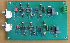
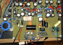
it is only an inter-step (functional sample, the resulting PCB will be smaller and include switches for input impedance, MC/MM etc.).
Yes, it might be possible to share the circuit, after all the tests.
it is only an inter-step (functional sample, the resulting PCB will be smaller and include switches for input impedance, MC/MM etc.).
Yes, it might be possible to share the circuit, after all the tests.
Onvinyl said:If you look at the datasheet of the LME 49713 at page six there is a plot of THD vs. output voltage. At 1mV we have 0.5% THD. That's what I'm talking about.
Rüdiger
Again I say...that distortion figure is a result of NOISE! See, distortion meters null out the fundamental and read everything left as distortion. At output levels that low, residual noise becomes the primary 'distortion'.
Measuse most any amplifier at 1 mv out and you'll see high distortion readings caused by noise.
The problem of NS is that they do not show spectrum analysis. THD+N for low levels is always dominated by noise, and is say nothing. One needs to have a circuit and make own evaluation. I was pretty disappointed with 49710.


Indeed, when they look like that it's all noise but is it interesting really to know the harmonics when they are so extremely small?PMA said:The problem of NS is that they do not show spectrum analysis. THD+N for low levels is always dominated by noise, and is say nothing.
In what way?PMA said:I was pretty disappointed with 49710.
I was testing many many opamps in a test circuit with low equivalent impedances (10R) in -IN and +IN, but noise gain 80dB. These NS circuits were very sensitive to interference products - TV row frequency and FM pilot frequency (demodulation, detection in input stage?). Also to USB packets frequency interference.
Well, regarding noise, the corresponding plot of the 49710 is way better. Maybe the 49713 guys had a noisier day...
Rüdiger
Rüdiger
Pavel, was this a really suitable test? I mean you could tell differences but how about in a real circuit?
Who knows? I like the circuits that are not influenced that much by interferences, and I do not think much about THD wars at 0.00001% level. I tend to agree with Charles Hansen.
PMA said:Gentlemen,
I would like to open a discussion on this topic.
MC phono preamp, solid-state.
ACD said:This will be interesting 😉
I suggest we choose to go for an opamp version,
then it must be active equalization with BTJ buffered balanced output.
Hello.
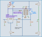
There are some nice low-noise ideas in an old National Application Note:
National AN-222 ( 1979 )
It is ways to use low noise monolithic dual transistors for lowest noise.
Today we have even better such duals. Both JFET and BJT.
I do not know if attached idea captured from AN-222 as a standalone would be for MC.
But for MM cartridge I think it will perform very well.
I am sure people with MM based pickups will read this topic with interest, too.
So I post a couple of posts.
Lineup 🙂
-------------------------------------------------------------
Some Low noise Designs web stuff, PDF:
AN-222 Super Matched Transistor Pair Sets New Standards for Drift and Noise
National Amplifier Application Notes - downloads
Attachments
🙂
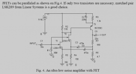
Here is another 'old idea'.
It is a capture of a most low noise and interesting circuit.
All discrete with matched monolithic JFET parallelled as input.
Capture from this Paper by Janasek:
Hompage: www.janascard.cz
Design of ultra low noise amplifiers - Vojtěch Janásek
Lineup 🙂
Here is another 'old idea'.
It is a capture of a most low noise and interesting circuit.
All discrete with matched monolithic JFET parallelled as input.
Capture from this Paper by Janasek:
Hompage: www.janascard.cz
Design of ultra low noise amplifiers - Vojtěch Janásek
Lineup 🙂
Attachments
scott wurcer said:Thank's for finding that 🙂 A lot of people attribute the input stage on that last circuit to an 80's AES paper. I had been searching through our Analog Dialog archives and missed it.
It's funny the way these things work - I had had that sitting in the PDF reader for, at a guess, maybe a week. I'd come across it in some other thread, presumably something here in the SolidState division, but possibly not - I'd been wandering pretty widely, following the occasional crosslink into some other thread with crosslinks into yet another...
I don't think I'd bookmarked it (d'oh) and had to beg Google for a lead. Luckily I had the title and some authors' names that were less common than Smith or Jones...
Bonsai said:BTW, John Atkinson did a review of a phono stage about a year back that used the passive approach (solid state I have to say) and remarked that it had a great sound, but overload capability was only 6dB.
This was a very misleading measurement.
I recall the review in question. Basically, the circuit had a lot of gain and the supply rails were something relatively low, like +/- 8 volts or so. This means a maximum output level of ~5 Vrms, and the large amount of gain combined with a high input signal level so that the unit was near to clipping to begin with. It didn't take much extra input ("headroom") to clip the output of the unit.
Now, 5 Vrms is plenty of output to drive a line stage, so I don't think that's an issue. Basically, JA should have either lowered the gain on the unit (I believe it was adjustable) or else used a lower input signal level.
The entire "headroom" issue is much more complex. In the old days (pre-MC), all MM cartridges put out about 5 mV and all phono stages had a standard gain of 34 dB.
The thing to watch out for is *input* overload, as that can be a problem. But the way these tests are done these days often only shows output overload (clipping), which doesn't really illuminate anything.
- Status
- Not open for further replies.
- Home
- Source & Line
- Analogue Source
- Solid state phono preamp design philosophy