Sure. I'm just trying to understand the added risk of one part that is placed in steeple fashion versus touching any other part on the board (ends of resistors, solder pads etc).
That's you not understanding what the circuit is doing..........................
First, in my case I need to use the larger 1N5359B because the average current through the zener post relay triggering is circa 57mA RMS and dissipation is circa 1.5W. While I realised this I had left the 1N4749A in the model as, frankly, I had not anticipated having to futz with this so much.........................
Andrew, C1 is the same for the store's BoM (0.01uF) and C2 is 1.5uF as per earlier discussion. Neither affect the voltage across the relay coil.
You have to ask the simulator the right questions to be able to see the right answers.
I ask again.
Have you adopted the mains feed capacitor selected for 120Vac and stuck the same component into a 240Vac fed supply?
Doubling the Mains voltage requires the capacitor to present double the impedance (represented by Xc) so that the current passing remains about the same.
It's not quite halving, but asking the right questions will lead you to a suitable cap value.
I learn. It's good that observing the output of the sim focused my attention on this detail of the circuit, the finer points of zeners and the constraints imposed by hysteresis.
I reply again reminding you that this was discussed some time ago. The size of C2 is one of the available controls for managing timing (alongside R3). Set it lower for slower delay. In my case, as noted earlier, I only need and prefer a much shorter delay. C2=1uF as per the BoM for the store's circuit (which, by the way, does not reference mains conditionality at all which I think is a problem; I think a lot more care should be taken with respect to the BoM for the store's board) and the delay is longer than it need be in my case. 1.5uF is better. (Recall I asked a question regarding fitting the larger 2uF on the existing board.) The selection of C2 isn't a case of matching size to mains voltage but rather matching size to required/desired timing (recognising, of course, the impact of a different mains voltage). The sim helps a lot in this regard.
I reply again reminding you that this was discussed some time ago. The size of C2 is one of the available controls for managing timing (alongside R3). Set it lower for slower delay. In my case, as noted earlier, I only need and prefer a much shorter delay. C2=1uF as per the BoM for the store's circuit (which, by the way, does not reference mains conditionality at all which I think is a problem; I think a lot more care should be taken with respect to the BoM for the store's board) and the delay is longer than it need be in my case. 1.5uF is better. (Recall I asked a question regarding fitting the larger 2uF on the existing board.) The selection of C2 isn't a case of matching size to mains voltage but rather matching size to required/desired timing (recognising, of course, the impact of a different mains voltage). The sim helps a lot in this regard.
Last edited:
I don't agree.
The mains capacitor is selected to supply adequate current.
Making it bigger than required for the current leads to over voltage on the low voltage side.
That's why your Zener is having to work so hard.
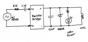
The supply voltage is 240Vac= Vin
The Low voltage side is 24Vdc = Vout
The bridge multiplies the AC to become a peak charging voltage ~ 1.4Times.
That leaves the voltage across the bridge as 24/1.4 + bridge volts drop
i.e. ~ 18 to 19Vac is the back emf of the bridge = Vbr.
Xc = 1 / 2piFC = 1 / 2*3.14*50*1.5 10^-3 = 2122ohms
You have Iac = [Vin - Vbr] / Xc
Iac = 240-19 / 2122 = 104mAac
That is far too high for a 24Vdc relay. All the surplus is being burnt off by the Zener.
Your relay needs ~33mAdc, design for that plus a little bit of spare to take account of variable Vin and other tolerances.
Forget about speed of closing.
Think about how to make the direct to mains safe by avoiding overvoltage on the low voltage side.
eg.
when Vin = 253Vac and we are drawing 40mAac through the capacitor, we can calculate that the voltage available at the bridge is
Vin - [Xc * 0.04] = 253 - 2122*0.04 ~ 168Vac
Why ignore this massive overvoltage?
The mains capacitor is selected to supply adequate current.
Making it bigger than required for the current leads to over voltage on the low voltage side.
That's why your Zener is having to work so hard.
The supply voltage is 240Vac= Vin
The Low voltage side is 24Vdc = Vout
The bridge multiplies the AC to become a peak charging voltage ~ 1.4Times.
That leaves the voltage across the bridge as 24/1.4 + bridge volts drop
i.e. ~ 18 to 19Vac is the back emf of the bridge = Vbr.
Xc = 1 / 2piFC = 1 / 2*3.14*50*1.5 10^-3 = 2122ohms
You have Iac = [Vin - Vbr] / Xc
Iac = 240-19 / 2122 = 104mAac
That is far too high for a 24Vdc relay. All the surplus is being burnt off by the Zener.
Your relay needs ~33mAdc, design for that plus a little bit of spare to take account of variable Vin and other tolerances.
Forget about speed of closing.
Think about how to make the direct to mains safe by avoiding overvoltage on the low voltage side.
eg.
when Vin = 253Vac and we are drawing 40mAac through the capacitor, we can calculate that the voltage available at the bridge is
Vin - [Xc * 0.04] = 253 - 2122*0.04 ~ 168Vac
Why ignore this massive overvoltage?
Last edited:
Forget about speed of closing.
Think about how to make the direct to mains safe by avoiding overvoltage on the low voltage side.
Don't forget R1 in your calculations.
What is unsafe about asking, at the high end of mains voltage range, a 5W zener to dissipate 1.4W, asking a 1A/3W rectifier diode to support 82mA and dissipate 37mW?
Yes, R1 needs to step up from 3W to more like 5W if it is asked to dissipate just under 3W with C2=1.5uF. (1.3W if C2 is left at 1uF.) Is that a big deal?
The size of C2 is one of the available controls for managing timing (alongside R3)
C2 has nothing to do with timing, this cap limits current to what is needed by the relay...
the impedance of C2 determines current supplied to the relay, roughly, I = 230v/Zc2.....
C3 is the cap that determines timing, increase it and you have more delay...
MASSIVE OVERVOLTAGE in a circuit fed directly from the MAINS.
A fault in a component could end up with dozens, or even hundreds of excess volts, that were not designed for !!!!!
A fault in a component could end up with dozens, or even hundreds of excess volts, that were not designed for !!!!!
C2 has nothing to do with timing, this cap limits current to what is needed by the relay...
the impedance of C2 determines current supplied to the relay, roughly, I = 230v/Zc2.....
C3 is the cap that determines timing, increase it and you have more delay...
This isn't correct. The slope dV/dt of the rising waveform across the relay coil, is proportional to the ratio (Cin/Cout), as in all charge pumps. The steeper the slope, the sooner the relay pulls in. The shallower the slope, the later the relay pulls in.
Changing Cin changes the (Cin/Cout) ratio, so it changes the slope, so it changes the relay timing.
Changing Cout changes the (Cin/Cout) ratio, so it changes the slope, so it changes the relay timing.
Some people like to think of Cin as a supplier-of-current. The bigger the Cin, the greater the current it can supply. This current charges Cout, resulting in a rising waveform across the relay coil. The bigger the current, the steeper the slope, and the faster the relay coil pulls in. Thus Cin affects relay timing.
Other people like to think of Cin as an impedance, which delivers current to output capacitor (and zener diode) via the bridge rectifiers. To these people, the bigger the Cin, the lower its impedance. This impedance charges up Cout; the lower the impedance, the faster Cout is charged up. Increasing Cin decreases its impedance and steepens the slope of the rising waveform across the relay coil. Decreasing Cin increases its impedance and makes the slope of the rising waveform across the relay coil, less steep. Thus Cin affects the relay timing.
Pretty much everybody agrees that Cout, the big electrolytic capacitor in parallel with the relay coil, affects the slope of the rising waveform across the relay coil. Bigger Cout means shallower slope, smaller Cout means steeper slope. Thus Cout affects relay timing.
Voila we now realize, EVERYBODY agrees that both Cin and Cout affect relay timing.
- Charge pump people say "yes, waveform slope is proportional to (Cin/Cout), and the slope determines relay timing"
- Current-supply people say "Cin affects timing because bigger CIn means bigger current; Cout affects timing because Duh it's obvious"
- AC-impedance people say "Cin affects timing because bigger Cin means smaller impedance means steeper slope; Cout affects timing because Duh it's obvious"
Attachments
Last edited:
I'm glad we can all agree on that now (hopefully). I would add that R3 affects timing delay also.
To Andrew's point, okay, perhaps there are better mechanisms for adjusting timing delay than C2 (Cin in Mark's commentary above). Yet Andrew will also find that reducing the value of C2 from 1uF (store's PCB BoM) by 50% or even 1/3 to 0.67uF does not provide enough [choose from Mark's list above as to your preferred rationale] to trip the relay at the low end of UK mains voltage and the low end of the 1N5359 Zener spec (22.8V) even with reduced hysteresis. I take on board, however, that rather than increasing C2 it is better to leave it at 1uF and alter other components, e.g. reducing C3, to speed relay if indeed desired.
To Andrew's point, okay, perhaps there are better mechanisms for adjusting timing delay than C2 (Cin in Mark's commentary above). Yet Andrew will also find that reducing the value of C2 from 1uF (store's PCB BoM) by 50% or even 1/3 to 0.67uF does not provide enough [choose from Mark's list above as to your preferred rationale] to trip the relay at the low end of UK mains voltage and the low end of the 1N5359 Zener spec (22.8V) even with reduced hysteresis. I take on board, however, that rather than increasing C2 it is better to leave it at 1uF and alter other components, e.g. reducing C3, to speed relay if indeed desired.
I will explore if there is a suitable middle ground < 2.1V but > 0.
It looks to me that a Schottky diode to replace LED3 works. Perhaps a 1N5819. There may be a more refined answer, i.e. an item with higher Vf that still works, but I think I will leave it at that.
The circuit designer has two problems to solve:
diyAudio member AndrewT correctly remarks that input series capacitor Cin is the mechanism which transfers power (design problem 1). In fact power delivered is
Aha, we now realize that The Right Thing To Do™ is to choose Cin first. Find a balance point where the relay coil receives its required ~ 900 milliwatts, the (indicator LED + limiting resistor) receives its required 250-1200 milliwatts, and the zener diode's power never falls below 120 milliwatts nor rises above 1500 milliwatts, across all possible variations of mains voltage, Cin tolerance, zener tolerance, and relay coil resistance tolerance. The decision to use a 5W zener instead of 1W, was a great idea IMHO.
After Cin is chosen, the output filtering capacitor can be selected so that (Cin/Cout) gives the desired relay pull-in timing. Across all possible variations of mains voltage, Cin tolerance, zener tolerance, relay coil resistance tolerance, and Cout tolerance, an acceptable range of time-delay-before-relay-pull-in can be selected.
Boom, you're done. Circuit design isn't difficult, but it is painstaking.
- Transfer enough power from Mains_VAC to 24VDC, so that you can pull in the relay, light the LED, and bias the zener at a point where it can absorb the inevitable variations due to component tolerances and mains tolerances
- Pull in the relay at a certain time delay T after power-on
diyAudio member AndrewT correctly remarks that input series capacitor Cin is the mechanism which transfers power (design problem 1). In fact power delivered is
- proportional to Cin
- proportional to (Vmains - Vzener)
Aha, we now realize that The Right Thing To Do™ is to choose Cin first. Find a balance point where the relay coil receives its required ~ 900 milliwatts, the (indicator LED + limiting resistor) receives its required 250-1200 milliwatts, and the zener diode's power never falls below 120 milliwatts nor rises above 1500 milliwatts, across all possible variations of mains voltage, Cin tolerance, zener tolerance, and relay coil resistance tolerance. The decision to use a 5W zener instead of 1W, was a great idea IMHO.
After Cin is chosen, the output filtering capacitor can be selected so that (Cin/Cout) gives the desired relay pull-in timing. Across all possible variations of mains voltage, Cin tolerance, zener tolerance, relay coil resistance tolerance, and Cout tolerance, an acceptable range of time-delay-before-relay-pull-in can be selected.
Boom, you're done. Circuit design isn't difficult, but it is painstaking.
I suggest you change the nodename of the bridge rectifiers' anode, LED cathode, Zener anode, etc. .... The present name might induce some future copier to make a disastrous connection to the chassis.
Corrected schematic attached with one caveat: replace LED3 with a 1N5819
Attachments
Thanks for all the help everyone. I am learning a lot. Hopefully the discussion is useful to others as well.
Now I need to go back to my voltage regulator circuits which have been driving me around the bend. I found they needed at least 100mA quiescent to be stable and so added the appropriately sized resistor to ground to create this minimum load. I then thought it sensible to check the addition of load capacitance to reflect the ATX spec for output capacitive load. Adding a cap for each rail for these amounts, e.g. 8000uF for the 12V rail, in my model caused the rail output voltages to saw-tooth. Adding some series resistance to the 'load' cap removes the problem but I am still trying to understand why. I'm sure there's a sensible explanation and obvious to y'all but I haven't got to it yet.
Now I need to go back to my voltage regulator circuits which have been driving me around the bend. I found they needed at least 100mA quiescent to be stable and so added the appropriately sized resistor to ground to create this minimum load. I then thought it sensible to check the addition of load capacitance to reflect the ATX spec for output capacitive load. Adding a cap for each rail for these amounts, e.g. 8000uF for the 12V rail, in my model caused the rail output voltages to saw-tooth. Adding some series resistance to the 'load' cap removes the problem but I am still trying to understand why.
I'm sure there's a sensible explanation and obvious to y'all but I haven't got to it yet.
Last edited:
I'm sure you will post about it in a "Voltage regulator goes unstable when I vary Rload and/or Cload" thread. Tis not much relevant to soft start circuit design.
Sure - did not intend to pose the question here. I want to spend some more time with the regs myself first.
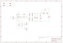
Is it just my PC at home or is the schematic pic I posted above very poor quality? I just used a Windows screen grab utility while in the office.
MASSIVE OVERVOLTAGE in a circuit fed directly from the MAINS.
A fault in a component could end up with dozens, or even hundreds of excess volts, that were not designed for !!!!!
that is why components have voltage ratings....ignore voltage ratings and you are in trouble...
working with 230 volt ac mains, caps rated for 630vdc can be used, caps rated for 1000vdc is even better...
This isn't correct.
replace C3 with a small transformer and you can forget about this cap....there are better options out there...

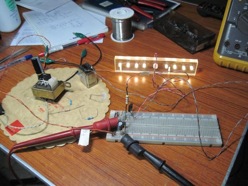
this is what i do in my amp....breadboarding for a 6 second delay..
That's the problem and I stated it, when I became aware of what the DIYaudio circuit was doing. DIYaudio did not like the criticism and I have paid for that numerous times since.....................
To Andrew's point, okay, perhaps there are better mechanisms for adjusting timing delay than C2 (Cin in Mark's commentary above). Yet Andrew will also find that reducing the value of C2 from 1uF (store's PCB BoM) by 50% or even 1/3 to 0.67uF does not provide enough [choose from Mark's list above as to your preferred rationale] to trip the relay at the low end of UK mains voltage and the low end of the 1N5359 Zener spec (22.8V) even with reduced hysteresis. I take on board, however, that rather than increasing C2 it is better to leave it at 1uF and alter other components, e.g. reducing C3, to speed relay if indeed desired.
It uses an RC from a variable voltage supply and that makes a very bad timer circuit.
You have copied this feature, so you are finding the same problem that is obvious by just looking at the circuit.
You should be using a timer that can tolerate variable supply voltage.
The Zener helps, but that is a band-aid.
A regulated LV, or a 555 style timer will perform far better.
Note that both the regulator (lm78xx, or lm317) and the 555 have maximum voltage limits that must be designed for.
Last edited:
But I don't have a problem with the circuit. I do agree that increasing C2 to obtain a faster relay activation was 'inefficient' versus changing C3 and thank you for highlighting that to me with persistence.
I'm sure there are many ways to skin the cat. Yes, I chose the DIYaudio circuit as a base to start with. Its timing is readily predictable and determinable. While indeed it varies within a range set by variances in mains voltage, giving it poor precision, that range is 'good enough' for me (and likely most others). I don't need it to be precise to the millisecond. All components are well within their limits.
I'm sure there are many ways to skin the cat. Yes, I chose the DIYaudio circuit as a base to start with. Its timing is readily predictable and determinable. While indeed it varies within a range set by variances in mains voltage, giving it poor precision, that range is 'good enough' for me (and likely most others). I don't need it to be precise to the millisecond. All components are well within their limits.
- Home
- Amplifiers
- Power Supplies
- Soft start circuit design and other psu issues