Yes I got to the answer last night. Of course, I was forgetting that current will flow across C1 given the AC source. I'm just too jumpy given it involves mains voltages.
The sim at max UK mains voltage (with dummy transformer and load removed) indicates 623uA through LED2 before the switch closes and a voltage of 2.6V at the 'control' capacitor C3. (68uA through LED1.) The 'pre-charging' of C3 shortens the time the NTC is in play by about 10% or so (which makes sense) but it's still circa 280ms before the relay trips (longer at lower mains voltages). I could increase the size of C3 but I don't think I will bother.
I'm not bothered by the LEDs being lit per se. I was more worried I had a problem... and given my nervousness because it's mains supply I was too hasty to post here.
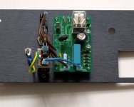
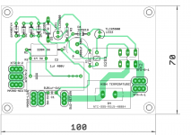
As built... 😉 With hindsight I would have laid out the soft start board differently but c'est la vie. I may still rotate the board 180 degrees.
Attachments

Last edited:
it looks fine as built....
like all things diy, you have to build it after so much talk.....😉
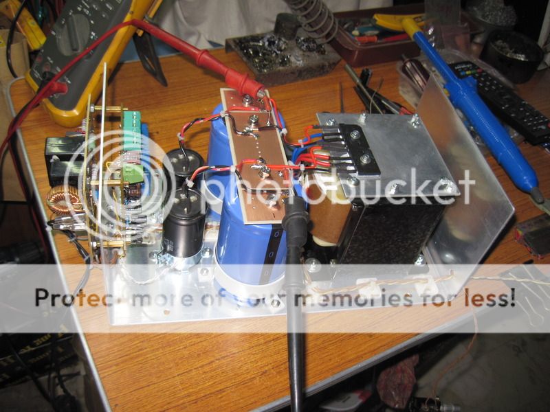
this is the rest of the build, my honey badger psu module...
quick connects are fitted with plastic sleeves so that no part of the ac line is exposed...
ac inlet on the left side, power switching on the right side, the other twisted pair is for the led panel light...
like all things diy, you have to build it after so much talk.....😉
this is the rest of the build, my honey badger psu module...
quick connects are fitted with plastic sleeves so that no part of the ac line is exposed...
ac inlet on the left side, power switching on the right side, the other twisted pair is for the led panel light...
Quite some time ago, I promised to post the Gerber files for the NTC-based soft start module I made with help here. I am finally doing so. Feel free to use but entirely at your own risk. This is a live mains voltage project. I have included the BoM that I used for my project in the zip file. Also, here is the link once more to the soft circuit LTspice models I made. Anyone using the PCB will have to verify that the circuit timing/part selection is suitable for their mains supply voltage and project.
Cheers
Steve
Hi Steve,
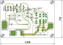
I tried to layout your schematic on a single sided board. What do reckon? Will it be good enough for diy style softstart PCB (etched at home)? I can get hold of Amatherm NTC's from a local supplier. Two (three🙂) questions..
1. whats the actual LED's currents? can 20mA rated be used here?
2. Can C2 be 400V "axial" polyprop cap? (one thats generally used for x-overs..)
3. can D6 be 1N4007 (instead of 1N5819)?
reg
Prasi
Attachments
Hi. Sorry my PM inbox was full. Should be ok now.
I have attached the sim files. Run softstart-hysteresis-ntc.asc. The LED currents will depend on coil resistance and Vf of the LEDs. As configured they rise to 30mA. But in addition to their current rating it is their Vf which is driving the hysteresis. A 1N4007 has a higher Vf than the 1N5819 but still less than the original TLCR5800. Have a read from post http://www.diyaudio.com/forums/power-supplies/262664-soft-start-circuit-design-other-psu-issues-5.html#post4086987 to understand what the driving factors are here.
Do you just need one or two boards? I have some spares of the v1.3 board. Send me a pm. If you are itching to etch your own board, you might at least consider replacing D1-4 with a DF10M. Your D6 and LED2 should be switched out of play when the relay trips.
Attachments
Last edited:
1. whats the actual LED's currents? can 20mA rated be used here?
2. Can C2 be 400V "axial" polyprop cap? (one thats generally used for x-overs..)
3. can D6 be 1N4007 (instead of 1N5819)?
1. yes...led current depends on the relay coil resistance..
2. if your mains is 230 volts nominal, use at least 630v or 1000 volts dc rated to be safe
3. yes but what for? that led should be able to pass the coil current....
1. yes...led current depends on the relay coil resistance..
2. if your mains is 230 volts nominal, use at least 630v or 1000 volts dc rated to be safe
3. yes but what for? that led should be able to pass the coil current....
Hi AJT,
1. Ok ... got it... If I use a RT424024 TE Connectivity / Schrack | Mouser relay (1.44 kOhms 16.7 mA), I should be able to use 20mA rated leds🙂.
2. yes, the mains is 230 nominal, will use 630V rated.
3. I am not sure when you say LED but the D6 as per schema (1N5819) is https://www.fairchildsemi.com/datasheets/1N/1N5818.pdf , Which I dont think I will be able get hold of. 1N4007 is universal🙂.
4.Also could the zener be of 1-2w rated (as absolute min)?
what I am trying to do here is to use most commonly and locally available parts.
with such low currents required, almost anything works....
i am iffy about the cap for supplying the rectifier bridge, i have seen failures even with 630 volt rated types so be very careful....
yes, zener dissipation is related to the cap, make the cap bigger and you will have bigger dissipation...
i am iffy about the cap for supplying the rectifier bridge, i have seen failures even with 630 volt rated types so be very careful....
4.Also could the zener be of 1-2w rated (as absolute min)?
yes, zener dissipation is related to the cap, make the cap bigger and you will have bigger dissipation...
with such low currents required, almost anything works....
i am iffy about the cap for supplying the rectifier bridge, i have seen failures even with 630 volt rated types so be very careful....
yes, zener dissipation is related to the cap, make the cap bigger and you will have bigger dissipation...
Thank you for your answers.
What would be a safe test methodology for softstart board (when first powering up- I can use MBT). But subsequently after removing the MBT, are there any other precautions to be taken (apart from the obvious- like being atleast 10 feet away😀). mine is a 800VA trafo with 50VAC CT and planned 40kuF-60kuF filter caps with MUR1560 rectifier.
I will post my planned BOM for this softstart tonight and would be glad if someone could comment.
reg
Prasi
3. yes but what for? that led should be able to pass the coil current....
The Vf of the LED and this diode combine to provide the level of hysteresis. One needs to manage this within the voltage rating of the relay for the low and high end of mains voltage. So this is the driving factor of component selection - of course they have to be rated for the current (which as noted rises to about 30mA or so...run the .asc and plot the LED current by probing it). The original design and v1.3 of the boards I did, provided for two LEDs here each with Vf of 2.1V. This was too much hysteresis at the high end of the mains voltage and so one of the LEDs was replaced with a low Vf Schottky diode.
Prasi, watch all your minimum clearances from edge of board etc. These are mains voltages.
Also, two of the principle timing controls (the length of time before the relay trips and bypasses the NTC) are R3 (smaller = longer delay) and C3 (larger = longer delay). I lowered R3 to 1K.
Also, two of the principle timing controls (the length of time before the relay trips and bypasses the NTC) are R3 (smaller = longer delay) and C3 (larger = longer delay). I lowered R3 to 1K.
Last edited:
Thank you for your answers.
What would be a safe test methodology for softstart board (when first powering up- I can use MBT). But subsequently after removing the MBT, are there any other precautions to be taken (apart from the obvious- like being atleast 10 feet away😀). mine is a 800VA trafo with 50VAC CT and planned 40kuF-60kuF filter caps with MUR1560 rectifier.
I will post my planned BOM for this softstart tonight and would be glad if someone could comment.
reg
Prasi
just make sure you did everything right....use a series mains lamp tester...
fyi, the Gas Ampzilla in the early 80's used a mechanical switching to soft start the amplifier...
the idea then was to limit surge current so as not to blow fuses
by introducing a series resistance to the traffo primary
which later is shorted out by the action of the rotary mains switch......
The Vf of the LED and this diode combine to provide the level of hysteresis. One needs to manage this within the voltage rating of the relay for the low and high end of mains voltage. So this is the driving factor of component selection - of course they have to be rated for the current (which as noted rises to about 30mA or so...run the .asc and plot the LED current by probing it). The original design and v1.3 of the boards I did, provided for two LEDs here each with Vf of 2.1V. This was too much hysteresis at the high end of the mains voltage and so one of the LEDs was replaced with a low Vf Schottky diode.
never had any of such issue in my builds...
modelling helps one be more precise and avoid the issues in the first place. Prasi can simply test for the Vf of the diode he'd like to use. I'd encourage him to spend a little time in LTspice with this simple circuit as a learning exercise. Two Vf of 2.1V was too much. 2.1V plus 0.6V was fine. 2.1V plus 1.1V? Have a look and see.
I think you will find that a 1N4007 will not work in that position. At the low end of mains tolerances Vrelay doesn't get high enough for the relay to trip and bypass the NTC.
Better to remove D6 from the circuit.
Better to remove D6 from the circuit.
I think you will find that a 1N4007 will not work in that position. At the low end of mains tolerances Vrelay doesn't get high enough for the relay to trip and bypass the NTC.
Better to remove D6 from the circuit.
Hi Steve,
I have included the 1n4007 and the relay RT424024 (http://www.mouser.com/ds/2/418/NG_DS_RT2_1014-728141.pdf).
I think the circuit works (remember, this is almost the first time I ever worked on LTS).
The relay voltage is just abt 24V, led currents are about 20mA. and zener current is 40mA( giving a dissipation of 0.96W.) . there is a momentary spike in zener current, will it create problems?
I have attached the sim files (have a look at softstart-hysteresis-ntc-prasi.asc).
Tell me if I am in the right direction and reaching right conclusions🙂.
reg
Prasi
Attachments
Prasi, watch all your minimum clearances from edge of board etc. These are mains voltages.
Also, two of the principle timing controls (the length of time before the relay trips and bypasses the NTC) are R3 (smaller = longer delay) and C3 (larger = longer delay). I lowered R3 to 1K.
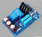
Have a look at attachment 1. Are people really using these things (they are plenty on aliexpress😱). Must be a safety nightmare ... with bare metal fuse holders.
attachment 2 , mine, improved with min 200mils from edges. 100 mils minimum between pads -traces, etc, except LED's.
reducing R3 to 1k, increases current in D6 (21mA) and reduces zener current.
reg
Prasi
edit: relay is not G2R2... its above TE connectivity part.
Attachments
Last edited:
I can't look at your file just yet but note the very different coil resistance rating of that relay: 1440 Ohms. It also activates at 16.8V, 70% of nominal. (It releases at 10% of nominal.) In the .asc model I posted CoilRes is a variable. So the first thing you need to do is change this
.param CoilRes 1440
rather than 650. In the relay.lib file you will see the model for the relay being used RLY_2POW1. Von there is set to 0.8. You can change this to 0.7 and save it. Run for mains spec low and high.
.param CoilRes 1440
rather than 650. In the relay.lib file you will see the model for the relay being used RLY_2POW1. Von there is set to 0.8. You can change this to 0.7 and save it. Run for mains spec low and high.
had a look - looks good. I see you already changed CoilRes. Lowering Von just means it will trip sooner.
CTRL-R to rotate in LTspice. CTRL-E to mirror. If you run the sim then hold CTRL and hover over a part you will get a thermometer symbol.Click to plot power dissipation.
CTRL-R to rotate in LTspice. CTRL-E to mirror. If you run the sim then hold CTRL and hover over a part you will get a thermometer symbol.Click to plot power dissipation.
Last edited:
- Home
- Amplifiers
- Power Supplies
- Soft start circuit design and other psu issues