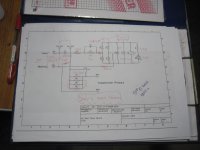
{on the simulation plot} Green is the primary side current going through the NTC. Pink is the primary side current going through the NC contact of the relay. You can see that the current limiter switches out after 300ms. ... Grey is the current through the first-in-line caps
Looks fine to me.
If you're still scared you can increase the limiter's resistance and increase the delay-before-bypass. In my opinion, what is shown is adequate and I'd leave it alone. But if you're desperate for more "safety," for more peace of mind, and if you can tolerate another half second of no-music-after-switch-on, go ahead and schmeer it out over a longer interval of time.
By the way, I think the waveforms would be a lot more frightening in a Class-A power amp (or a computer full of bipolar logic) which drew several amperes of load current at all times, even during power-up.
Last edited:
Thanks. The point I was trying to demonstrate is that while one is certainly free to add current limiters in different places, it is certainly also possible (and quite likely) that a single current limiter, with appropriate specifications, can handle, from source, both the magnetising current for the toroidal transformers and current charging the filter capacitance bank. 0.3s is over in the flashest of flashes (see the movie Love Actually) and, as Mark notes, could easily be extended if need. Size the NTC appropriately for the size of the job at hand and it is still working for you at 300ms or more.
Andrew decides to define "soft start" in a manner that suits his argument. (And Andrew if you once again say that sizeable NTCs are too expensive in the UK I will add a couple to my next Mouser order and send them to you free of charge so that you can never again argue such. 😀 )
Mark, regarding your very last point, of course power on of either can be delayed separately. In my case I couldn't switch the rear panel "mains on" switch and then press the front panel button in under 300ms unless I was incredibly determined (and even then, the computer can't turn on until the power rail voltages have come up to spec).
soft start and slow charging
right Andrew and perhaps the industry have been using them even before we were born....
right Andrew and perhaps the industry have been using them even before we were born....
Enjoy the semantics. It doesn't change the fact that an appropriately designed current limiter on the primary side can perform both functions.
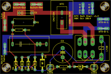
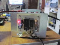
Quite some time ago, I promised to post the Gerber files for the NTC-based soft start module I made with help here. I am finally doing so. Feel free to use but entirely at your own risk. This is a live mains voltage project. I have included the BoM that I used for my project in the zip file. Also, here is the link once more to the soft circuit LTspice models I made. Anyone using the PCB will have to verify that the circuit timing/part selection is suitable for their mains supply voltage and project.
Cheers
Steve
Cheers
Steve
Attachments
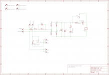
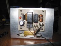
You know, in hindsight it might have been smaller or more elegant, to use a 4-diodes-in-one-package bridge rectifier instead of four 1N4007s. Here we see a 1.5A, 1000V bridge in a dual inline package. It would be perfectly adequate to drive the coil of a relay and an LED.
I think I will leave that change to the next person - if it helps I can post the board and schematic files from Eagle.
PS: The TLCR5800 have notches in their legs which I presume is intended to elevate the LED off the board. If I have this incorrect please don't hesitate to let me know.
PS: The TLCR5800 have notches in their legs which I presume is intended to elevate the LED off the board. If I have this incorrect please don't hesitate to let me know.
Last edited:
It is your choice how high off the board you mount the LEDs. If Vishay put their little tabbie-thingies in a useful place, that's serendipitous good luck. If not you can ignore the tabs, or modify the drill hole size, or grind off the tabs with a Dremel tool before stuffing. Don't allow Vishay to dictate how you deploy their product once you've bought it. You are the designer and you make the choice.
even with the board laid out as is, still you can use inline pin bridge rectifiers if the builder wishes.....

or this..

or this..
Silly/basic question (but given safety is paramount I will ask it to be sure): should the fuse be placed (a) between IEC inlet and soft start board, (b) soft start and switch, or (c) between soft start and transformer? I assume (a) but would prefer confirmation from more experienced users...
I would put the fuse in position (a), between the AC mains inlet and everything else. Since the soft start board limits inrush current, I would be inclined to fit a fast-blow type of fuse.
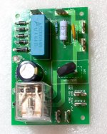
Ok I just got a bit of a surprise when I tested the board in post #268 (circuit in #267). I wasn't expecting any of the LEDs to light up until the switch was closed. Instead they're both lit when the switch is open. Closing the switch brightens both until LED2 is bypassed (along with the NTC) and it extinguishes.
Am I misunderstanding the impact of C1 in an AC environment or do I have a problem? Either way, it wouldn't seem ideal as presumably C3 has some charge and so the circuit will trip sooner than desired?
Am I misunderstanding the impact of C1 in an AC environment or do I have a problem? Either way, it wouldn't seem ideal as presumably C3 has some charge and so the circuit will trip sooner than desired?
You simulated this numerous times. What was the simulated value of current that flows thru capacitor C1 when the switch is open? What was the simulated value of current that flows thru LED1 when the switch is open? What was the simulated value of current that flows thru LED2 when the switch is open?
Are the simulation values of LED current, sufficient to light up a real LED? You could try it on the bench with your adjustable DC power supply, a 10K resistor, your digital multimeter configured as a milliammeter, and a matching LED.
You could experiment on the bench and find out how much current you can squirt thru your LEDs and yet still perceive them as "dark". Then use this as a new design constraint to find new values for C1, C2, R1, R2 which keep the LEDs "dark" when the switch is off, yet which pull in the relay when the switch is on and the mains is 10% low and all resistors are at the upper limit of their resistance and the relay coil is at the lower limit of its resistance etc.
Last edited:
- Home
- Amplifiers
- Power Supplies
- Soft start circuit design and other psu issues