I suggested you measure a relay and give up the simulator.
I'll explain.
You can use a simulator when you understand the operation of the circuit and know what questions to ask and know how to interpret the answers it gives to your questions.
If any part of those three levels of understanding are missing then a simulator is worthless.
Learn how a relay works first, then model it's behaviour.
When the model matches your measurements, then increase the complexity of the model. That's when the simulation package really comes in handy.
here's your example of a level of understanding that is missing
Why does the simulator give a different answer? Ohm's law can't be wrong. Where is the error in the report, where is the error in your interpretation of the reported result?
What is happening in the simulator model that you had ignored?
I'll explain.
You can use a simulator when you understand the operation of the circuit and know what questions to ask and know how to interpret the answers it gives to your questions.
If any part of those three levels of understanding are missing then a simulator is worthless.
Learn how a relay works first, then model it's behaviour.
When the model matches your measurements, then increase the complexity of the model. That's when the simulation package really comes in handy.
here's your example of a level of understanding that is missing
using simple ohm's law what current would you expect to flow through the relay coil? use a calculator to ease the arithmetic.need I worry about this very slightly higher-than-rated modeled current through the coil with the existing circuit for which I have boards on the way?
Why does the simulator give a different answer? Ohm's law can't be wrong. Where is the error in the report, where is the error in your interpretation of the reported result?
What is happening in the simulator model that you had ignored?
Last edited:
Andrew, of course. Yet simulation can also be a powerful learning tool. (It sure as hell beats some of the guesses that have been made as to how long the relay takes to trip in the store's soft start board.)
Unsurprisingly, the sim's projected current through the coil exactly coincides with Ohms law given the coil resistance (650R) and the voltage across it. (Lord help us if they got that wrong.) RMS voltage of 25.29V and current of 38.9mA.
Unsurprisingly the "rated current" and "rated voltage" conform to Ohm's law given the coil resistance rating of 650R. I could have expressed my question via current, i.e. is 38.9mA versus a "rated current" of 36.9mA too high, or voltage, i.e. is a voltage across the coil of 25.29V too high versus a "rated voltage" of 24DC. I could have asked whether it was necessary to add a 35-50R series resistor to lower the voltage seen by the relay. (Now, of course, my little model does not take account of trace resistance but I suspect these may well be small versus the 35 Ohms of resistance needed to drop 1.3V+.) Or perhaps you have identified some other error in the simulation which means the voltage seen by the relay is indeed lower than 24V? Or perhaps 25.3V versus a rated 24V isn't worth worrying about?
I don't yet have the relay so physical measurements aren't available to me as of yet. What would you propose I measure when I do?
Does the relay driver use a saturated transistor as the switch?
That will account for between 30mV and 150mV at the switch.
or
does the driver use a Darlington as the switch?
That will account for between 750mV and 900mV at the switch.
That extra 600mV or so, will heat up the Darlington and waste drive voltage.
The output from the Driver PSU will depend on the current drawn before the switch closes and after the switch closes.
This can only be measured on the actual build. BUT !!!! be careful as far as I know it is still a direct to mains project, which is normally banned on this Forum.
I thought the LY2-0-DC24 was a simple electromagnetic relay, i.e. electric current through the coil creates a magnetic field which then activates a mechanical armature. Break the magnetic field and the armature returns to its original position. There's not much in the documentation as to it's construction but it does include references to armature and characteristics including mechanical operations per hour. Maybe I have this wrong or, again, I'm misunderstanding what you are saying.
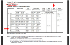
Usually it is a splendid idea to read the datasheet. I pulled out a random relay datasheet just now, and found these little tidbits (excerpt attached):
This might be simple. Or it might require a tighter-than-10%-tolerance Zener diode. Or I might just measure a handful of cheap Zeners and select one that meets my requirements.
_
- The coil resistance is guaranteed to fall somewhere in the range 552 < Rcoil < 747 ohms
- The relay is guaranteed to pull in if Vcoil >= 19.2 volts. (sooner? possibly, but this is not guaranteed)
- The maximum voltage you are permitted to apply across the relay coil is 26.4 volts
This might be simple. Or it might require a tighter-than-10%-tolerance Zener diode. Or I might just measure a handful of cheap Zeners and select one that meets my requirements.
_
Attachments
gdamn, I don't know how many times I looked at that table without noticing max voltage...I even had to enter the must operate and must release ratings into the model. 😱
I found post50.Does the relay driver use a saturated transistor as the switch?
That will account for between 30mV and 150mV at the switch.
or
does the driver use a Darlington as the switch?
That will account for between 750mV and 900mV at the switch.
That extra 600mV or so, will heat up the Darlington and waste drive voltage.
The output from the Driver PSU will depend on the current drawn before the switch closes and after the switch closes.
This can only be measured on the actual build. BUT !!!! be careful as far as I know it is still a direct to mains project, which is normally banned on this Forum.
Is that your circuit?
You don't have a transistor switch, just a slow build up of voltage as the mains capacitor passes a bit of current.
Post #148.
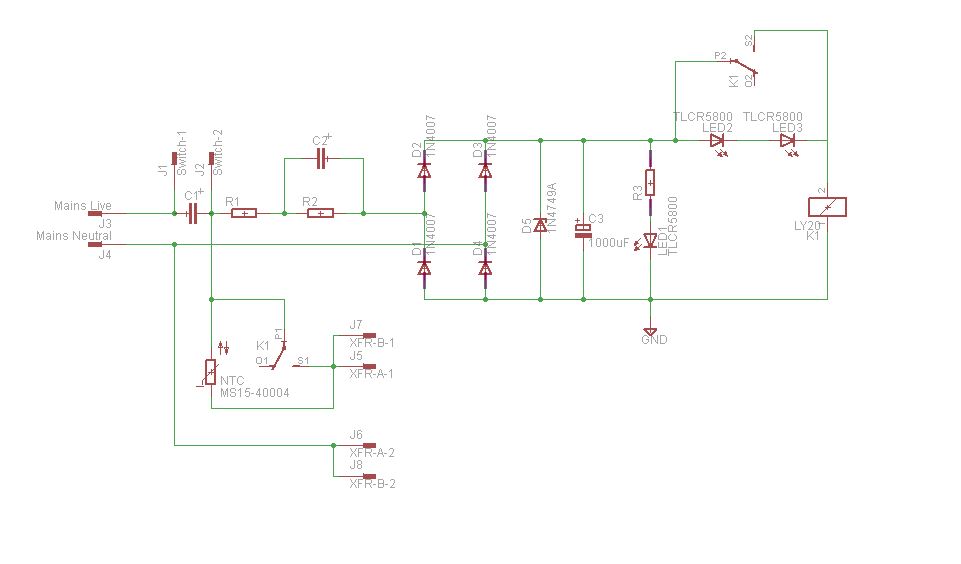
C1 should be much much lower than C7(about 0.001ufd) and rated for 2kv at least since it will be quenching switch sparking at turn off/turn on...
R1 is not really required...
C7 delivers the charge needed to actuate the relay coil, it should be sized big enough to power the relay and bias the zener diodes with some current..
i use NTC resistors in my amps....i leave them alone in circuit..never had a failure with them in circuit all the time...
For my intended use they need to be switched out.
I presume you mean C2 when you write C7. For C1 I was planning to use the same component as in the BoM of the store's board. This circuit was merely an adaption of that circuit to use an NTC instead of a resistor bank and add the hysteresis suggested by Mark. That's why the conversation started in that thread - I began by modelling the timing behaviour of the store's circuit.
I presume you mean C2 when you write C7. For C1 I was planning to use the same component as in the BoM of the store's board. This circuit was merely an adaption of that circuit to use an NTC instead of a resistor bank and add the hysteresis suggested by Mark. That's why the conversation started in that thread - I began by modelling the timing behaviour of the store's circuit.
yes, C2 it is....
for an event that takes place 1 or 2 seconds....no need to be too concerned....
for an event that takes place 1 or 2 seconds....no need to be too concerned....
I suggest you change the nodename of the bridge rectifiers' anode, LED cathode, Zener anode, etc. Call it Maggie or Jane or Debra or Kate or Liz. The present name might induce some future copier to make a disastrous connection to the chassis.
I'd also want to guarantee that the highest voltage my zener supply could output (worst case Zener @ top end of spec range, high mains voltage, low rectifier Vfwd) was comfortably below 26.4 volts.
With 358V peak mains voltage and with BV and Vpk in the Zener model set to the upper end of the 22.8-25.2V range of the 1n4749A (i.e leaving the 1N4007 rectifier diode untouched at its standard model) voltage across the coil reaches 26.7V versus 110% of 24V = 26.4V.
The Zener model used is:
.model 1N4749A D(Is=1n Rs=25 Cjo=50p nbv=3 BV=24 Vpk=24 Ibv=10.5m mfg=Fairchild type=zener)
and I simply changed BV and Vpk to 25.2.
I'm surprised at how high peak voltage is with the Zener in the circuit. With Vpk and BV returned to 24V, and mains voltage of 358V peak, measuring Vrelay after the relay has tripped yields:
Peak: 25.662
RMS: 25.538
remove R3:
Peak: 25.741
RMS: 25.616
remove the cap:
Peak: 27.657
RMS: 24.34
Intuitively I was expecting these to be lower.
What is the worst case current through the Zener?
Then check Pdissipated.
Maybe the capacitor to the Mains is too large.
Have you adopted the cap value used for 110/120Vac Mains?
Then check Pdissipated.
Maybe the capacitor to the Mains is too large.
Have you adopted the cap value used for 110/120Vac Mains?
Perhaps this is just a modelling issue combined with an insufficient understanding of zener diodes... ;-)
First, in my case I need to use the larger 1N5359B because the average current through the zener post relay triggering is circa 57mA RMS and dissipation is circa 1.5W. While I realised this I had left the 1N4749A in the model as, frankly, I had not anticipated having to futz with this so much.
Replacing the zener diode with:
.model 1N5359B D(IS=1.54e-17 N=1 XTI=1 Rs=.1 Cjo=10p TT=10n BV=24 IBV=50m NBV=35 Vpk=24 mfg=OnSemi type=Zener)
gives more sensible looking results. (I merely amended the included model for an On Semi 1N5369B by changing BV, Ibv and Vpk. All other variables except NBV are the same across the included 1N53* range. I am unsure if NBV is available on the data sheet.) Then adjusting BV and Vpk to the upper limit of BV in the data sheet (25.2V) gives Vrelay of 25.3V, now inside the 110% limit. Vrelay and BV are now more sensibly aligned (post relay tripping).
I presume the key issue is the difference in Ibv? I had understood this as merely being the test current at which reverse breakdown occurred... I presume I have underestimated its importance in modelling this little thing.
Andrew, C1 is the same for the store's BoM (0.01uF) and C2 is 1.5uF as per earlier discussion. Neither affect the voltage across the relay coil.
In SPICE you can sweep the IV curve of your modelled 5 watt zener and make sure you've got the proper dynamic impedance @ the datasheet test conditions. If it matches the datasheet knee voltage and also matches the datasheet dynamic impedance, all is well.
More generally you are beginning to notice that the hysteresis voltage eats up some of your margin of safety.
If mains voltage variations + unit_to_unit variations in zener voltage Vz, result in a filtered output voltage window of (Vmin to Vmax), then you are asking the relay to do two things:
Fortunately you can replace one or both hysteresis LEDs on your PCboard, with conventional silicon diodes (or >40V Schottky diodes), as long as you put an insulating sleeve over the exposed lead. And of course you could replace one or both LEDs with resistors too. Even zero ohm resistors. Put an insulating sleeve over the exposed lead.
More generally you are beginning to notice that the hysteresis voltage eats up some of your margin of safety.
If mains voltage variations + unit_to_unit variations in zener voltage Vz, result in a filtered output voltage window of (Vmin to Vmax), then you are asking the relay to do two things:
- Always pull in when Vcoil = (Vmin - Vhysteresis)
- Never melt or suffer reduced reliability when Vcoil = Vmax
Fortunately you can replace one or both hysteresis LEDs on your PCboard, with conventional silicon diodes (or >40V Schottky diodes), as long as you put an insulating sleeve over the exposed lead. And of course you could replace one or both LEDs with resistors too. Even zero ohm resistors. Put an insulating sleeve over the exposed lead.
In SPICE you can sweep the IV curve of your modelled 5 watt zener and make sure you've got the proper dynamic impedance @ the datasheet test conditions. If it matches the datasheet knee voltage and also matches the datasheet dynamic impedance, all is well.
Thanks. Good idea. I will give that a go.
More generally you are beginning to notice that the hysteresis voltage eats up some of your margin of safety.
Indeed. I was just now looking at the 'low end' case. The level of hysteresis needs to be reduced. All of this is a good lesson in running through all the 'boundary' permutations.
Put an insulating sleeve over the exposed lead.
Why is this necessary? Were they conventional through-hole diodes in the first place there would be a small piece of exposed lead on either end of the diode in any event. Is it because in this case the lead would be extended? I was thinking of just jumpering one of the LED positions. (I like the idea of at least one LED as a visual confirmation of the relay bypassing.) It would still leave 2.1V of hysteresis.
I was thinking of just jumpering one of the LED positions.
I guess I needn't be so quick. I will explore if there is a suitable middle ground < 2.1V but > 0.
I'm still curious re the sleeving point. * Can it be simple heat shrink?
* edit: to avoid a knock shorting out the hysteresis Vf?
Last edited:
The soft start PCBoard is directly connected to the lethal AC mains. Spend 1 New Pence and 3 minutes of your time, protecting anyone who might possibly come near the board.
- Home
- Amplifiers
- Power Supplies
- Soft start circuit design and other psu issues