Thanks. Can I test it with a bench psu or it will need AC input only?
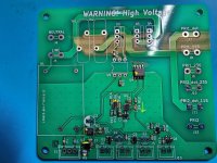
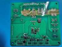
As for the AC out J6 is hot and J8 is neutral?
As for the AC out J6 is hot and J8 is neutral?
a gentle correction. There isn't a triac in this version. When power is first applied the current is limited by the NTC's and after a few second delay they are bypassed.
Thanks for the correction Jhofland. Forgetting which versions I am looking at.
@voxxonline - you need 110vac to 230vac in order to get the 5v from the AC/DC module. However, if you provide 5v externally from bench supply to the output of the AC/DC, you can test it without mains. The back to back MOSFETs will work with either AC or DC. But easiest to just plug it into the wall mains.
@voxxonline - you need 110vac to 230vac in order to get the 5v from the AC/DC module. However, if you provide 5v externally from bench supply to the output of the AC/DC, you can test it without mains. The back to back MOSFETs will work with either AC or DC. But easiest to just plug it into the wall mains.

Hi @xrk971,
can I use this LED:
https://www.mouser.com/ProductDetail/Lite-On/LTL-1CHG?qs=sGAEpiMZZMt82OzCyDsLFH74SbLY4iG0AGBUvP5lYCw=
instead of this (from BOM):
https://www.mouser.com/ProductDetail/Lite-On/LTL-4236N?qs=%2BY%2Bm5kuB5aiB3WZbX23AGA==
?
The difference in Operating Supply Voltage is bothering me.
can I use this LED:
https://www.mouser.com/ProductDetail/Lite-On/LTL-1CHG?qs=sGAEpiMZZMt82OzCyDsLFH74SbLY4iG0AGBUvP5lYCw=
instead of this (from BOM):
https://www.mouser.com/ProductDetail/Lite-On/LTL-4236N?qs=%2BY%2Bm5kuB5aiB3WZbX23AGA==
?
The difference in Operating Supply Voltage is bothering me.
Hello Forum members,
I am currently sourcing parts for the SFPP board with on/off capability. I have been able to track down all the components except one. The original SOT-23 Mosfet from Onsemi seems to be out of stock everywhere I look. Can anyone tell me if the following version of this component would work? It looks identical to me, but I want to be sure, given the difficulty of rework on these SMD's if I am wrong.
Thank you in advance for your help. Dave M.
https://www.mouser.com/ProductDetail/onsemi/BVSS138LT1G?qs=3PKVEWFFm2%2B4AZCAVE9dYQ==
The onsemi version is not critical. Almost any one of them in a SOT-23 package from a reasonable vendor will work well. For example, the Nexperia BSS138P,215 or a Diodes Inc BSS138-7-F. Mouser shows ample stock of both.
Those are just small signal MOSFETs for logic control. I think the part you found should work just fine as specs are identical. Note that they have 2M in stock so it’s a commonly used part.
Edit: just saw that Jhofland responded already.
Edit: just saw that Jhofland responded already.
Hello Forum Members,
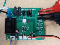
Looking for feedback. I'm wondering if anyone with more experience building the SFPP soft-start board would care to take a look at the orientation of my IC's and diodes.
Also, feel free to offer feedback on the soldering quality. I used the hotplate/hot-air wand method which worked very well. Unfortunately, I used too much solder paste and had to go back with braid to fix bridges on the IC's. I still think I see one on U4.
Oh my gosh, these are some small critters to work with for aging eyes and hands! I have to say though, I really like the smaller footprint of pcb's that use them.
Thanks folks!
Attachments

Hi UncleMud,
Nice first attempt. As you saw, much less solder paste is needed. Also I think your temps were not high enough as some joints don’t look like a smooth fillet or ball. I would suggest going over the small IC pins with copper braid soaked in flux with a chisel tip iron on top of the braid to soak up excess solder on the pins to prevent bridges. Especially U2 and U3. They are very sensitive. You will notice that once the ACDC is installed, it’s tough to get to one side of the pins on U3. So solder the AC/DC very lightly - almost just the tips of pins touching. This way, you can remove it easily to rework.
All the joints I circled need either solder braid and flux to remove excess solder or just go over with a hot iron to reflow the solder. It should form a smoother joint. You might have a cold solder joint on some of these. The LED orientation is hard to say unless you look at the bottom of it first.
Good luck!
Hello Forum Members,
Wondering if this switch from Parts-Express would be appropriate for the SFPP board? If not, any suggestions? Thanks!
https://www.parts-express.com/SPDT-...ush-Button-Switch-with-Red-060-659?quantity=1
Wondering if this switch from Parts-Express would be appropriate for the SFPP board? If not, any suggestions? Thanks!
https://www.parts-express.com/SPDT-...ush-Button-Switch-with-Red-060-659?quantity=1
Hello UM,
A non-latching momentary pushbutton switch works with this board. (NO,NC,C)
AC is not wired to the switch, low voltage DC is. There are two LED indicators on SFP+, Stand-By and ON. An LED fixed to the front panel can be the Stand-By indicator, the ON indicator can be an illuminated pushbutton switch.
I use these:
https://mou.sr/3Qj34q8
Hello Forum Members,
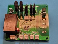
Well, I wired up my SFPP board for a test drive. It has some issues.
On a positive note, the switch Vunce suggested will look beautiful on my Honey Badger if I can successfully de-bug the board.
The switch does light up when cycled. The light also goes out properly when cycled. Howver, I have no illumination from the standby LED at anytime. Additionally, the board allows mains voltage to pass through at all times, regardless of switch position.
I have attached several pics in the hope they will be helpful. Any suggestions where I should start?
Thank you in advance! Dave M.
Attachments
Dave,
Connect a transformer to the SFPP, it needs a load to work properly. If not connected you will get the results your showing. Just be sure the secondaries are not touching anything so no chance of shorting.
The standby LED could be as simple as reversed polarity.
Connect a transformer to the SFPP, it needs a load to work properly. If not connected you will get the results your showing. Just be sure the secondaries are not touching anything so no chance of shorting.
The standby LED could be as simple as reversed polarity.
- Home
- Group Buys
- Soft as a Feather Pillow (SFP) SSR Soft Start Circuit GB