Good morning fellow forum members,
I had hoped to be back online before now but other obligations have been slowing down my progress. So here is the update on my softstart testing. (And Thank You Anand for taking the time to lay out a very helpful bit of testing and wiring info).
I received my LED's from Mouser, installed one with the correct orientation and bingo; it lit up as expected. However, my testing results have me scratching my head.
I 'carefully' checked voltage on the underside of U1 and the DMM read 4.99 vDC. Pin 1 of U2 reads 4.99vDC, pin 8 of U3 reads 4.99vDC, pin 3 of U4 reads 4.99vDC. So what reading do I get accross J11? (0.69 vDC) I should be getting the same voltage accross J11 shouldn't I? I reflowed all of the solder joints in that area of the board to no avail. I also removed R14 and tested it, thinking that maybe I had the wrong value resistor. However, R14 tested out at 1004 ohms. Any thoughts before I start replacing parts wholesale? I do wear a carbon fiber wrist strap but could I have zapped one of the transistors?
Thanks in advance for your time and your ideas. Respectfully, Dave M.
Attachments
Hi UncleMud,
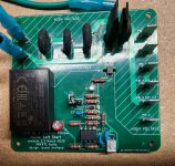
What you measure at J11 is the open collector logic to control the SSR’s. Note that 5v goes through the 1k resistor. It’s meant to provide a current loop through J11 to activate the optoisolator on the SSR speaker protect board. In normal operation this resistor provides 5mA of current to light up the LED in the optoisolator. When a trigger event occurs, the “open collector” comparator acts as a current sink and shuts off the current flow to SSRs by sinking that pin close to GND. That stops the 5mA current from activating the optoisolator in the SSRs. So I think what you have is normal. You can test this by putting an LED across J11 (anode to pin 1 and cathode to pin 2) and see that it lights up only after about a 2 second delay after turn on. I think all is good and you have a good working unit.
If you are using a low capacitance PSU for your SSR speaker project board that will handle the quick shutdown and it already has a built in 2 second turn on delay. So you don’t need to use J11. It is there for anyone who wants an open collector logic to integrate their own electronics for specific purposes tied to the SFP on state.
Last edited:

Thanks X. I will test with an extra LED, but that is good to know. I appreciate the response. I'm probably good to go then.
What type of terminal blocks are those that we can see in this photo?What toroid are you talking about?
You mean this?
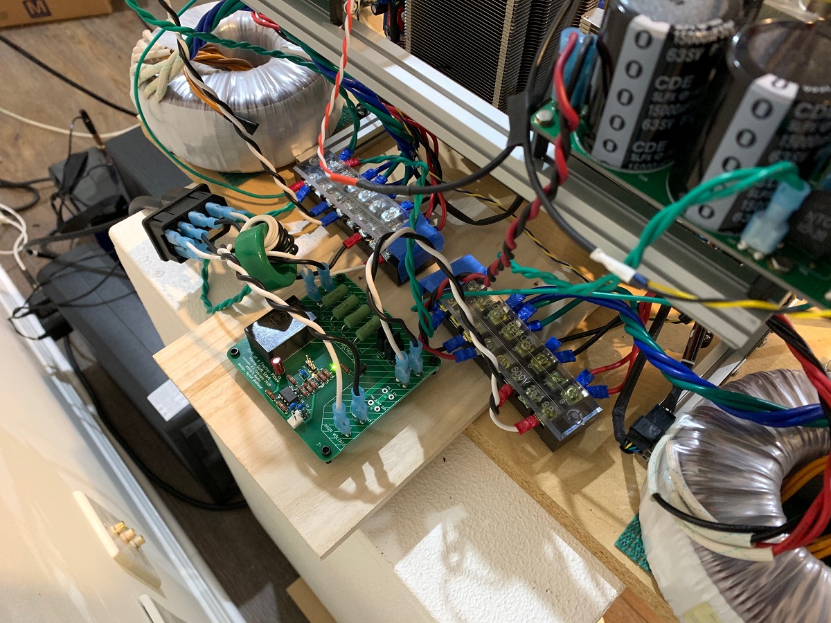
That’s not part of the SFP circuit. I just wrap my mains from the wall through that 2-3 turns in opposite directions for the line and the neutral as a common mode filter choke. These are eBay/Ali-Express circa 25mm ferrite donuts. No spec other than diameter. Similar to this:
https://www.diyaudio.com/forums/att...soft-start-circuit-gb-sfp-v2-1-gh-testing-jpg
Anyhow, it’s not needed for the SFP to work. I just use it to reduce RFI from the walls reaching my amp.
+ 1 for the next version of the board . . . .ok, that's good news!
One thing that would be very interesting to integrate to the circuit is a momentary switch driver with LED or dual color LED support. This is very useful for integrating a front panel switch without having to run AC there. Just a thought..
Thanks
Do
Go to Jeff Bezos’ website…plenty of examples there. MILAPEAK is a popular brand.What type of terminal blocks are those that we can see in this photo?
Best,
Anand.
Or Aliexpress. Lots of things under “terminal blocks screws”
For example
https://a.aliexpress.com/_mMBFJyA
For example
https://a.aliexpress.com/_mMBFJyA
Would these be OK: https://uk.rs-online.com/web/p/mosfets/8912958These are $3.79 and good for 11 A.
https://www.mouser.com/ProductDetail/Infineon-Technologies/SPP11N60C3XKSA1?qs=sGAEpiMZZMutXGli8Ay4kBTMNUyJlJ9tlkh6d8taGbA=
This has 0.35ohm RDson so will heat up somewhat. Probably will need a small heatsink vs RDson 0.025 ohm ones.
You can search for “TO-220-3 MOSFET low RDson”
I am actually using TO-247 with pins bent to fit TO-220. The key is voltage able to handle mains, so 250v to 450v and low RDson. Also handle the DC current of interest.
N channel, 31A, 600V, 88mOhm should all be fine.
Only dissipates 0.4W at 5A of current. Will stay relatively cool.
Only dissipates 0.4W at 5A of current. Will stay relatively cool.
I have had a chance to test out the SFP Plus (SFPP) a few more times now. It includes ability to be turned on/off with a momentary pushbutton switch, allows for thermal shutdown switch, and has logic to drive speaker protection SSR with open collector logic. Latest amp I am using it on is the Aksa Deltic.

This board has a lot of tiny SMT parts and is a bit tricky to assemble. This might be a good option for a ready to run (RTR) board. Or it would have to be redesigned with as much TH parts as possible. Or maybe just have the small SMT stuff preinstalled.
Nonetheless, it’s a sweet board and gives your amp a professional and very satisfying push button click on without throwing a big mechanical switch or relay. The LED ring light on the button comes on and is very nice.
It’s mounted on the top lid of the Deltic since I ran out of space.
I only have a hot plate (yet to try this method) and a temp controlled Hakko with a variety of tips to choose from. I've pulled off plenty of SOIC-8's, and 0603 components with just an iron. I'm more than willing to be a guinea pig and try a build with my less-than-ideal gear.
It’s the TSSOP8 with 0.65mm pitch that’s a bigger to solder. I have usually had to run a solder wick over it to remove bridges.
Having built several BTSB's, that SFPP looks quite straightforward from an SMD build standpoint - especially with a hot air station, henna nozzles and solder paste 🤓 .
Best,
Anand.
Best,
Anand.
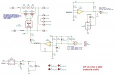
Here’s the schematic of the SFPP v2 by Jhofland:

Anand, I’m sure you would not have any trouble assembling this one.
I’ll probably offer it as a PCB for those willing to try making it themselves. One nice thing about it is there are not too many parts.
Anand, I’m sure you would not have any trouble assembling this one.
I’ll probably offer it as a PCB for those willing to try making it themselves. One nice thing about it is there are not too many parts.
- Home
- Group Buys
- Soft as a Feather Pillow (SFP) SSR Soft Start Circuit GB