Hi PinkFloyd4ever,
If you need a couple, I can send you some. Send me a PM. I think it is Toshiba TLP-3906.
If you need a couple, I can send you some. Send me a PM. I think it is Toshiba TLP-3906.
Shoot, now before I got my order in, I see that TH1-TH3 (SL15 10006) are now out of stock. What can I substitute for those that's currently in stock at Mouser? CL-60?
Or would one of these (7.5Amp, 10 Ohm) be better? https://www.mouser.com/c/circuit-protection/thermistors/inrush-current-limiters/?current rating=7.5 A&resistance=8 Ohms|~10 Ohms&instock=y
Or would one of these (7.5Amp, 10 Ohm) be better? https://www.mouser.com/c/circuit-protection/thermistors/inrush-current-limiters/?current rating=7.5 A&resistance=8 Ohms|~10 Ohms&instock=y
Last edited:
Those are fine. Even cheap 8D-20 NTCs from eBay work. 3x8 ohm or 3x 10ohm is fine. Current at least 5A or so.
Hi Folks,
I see there has been quite a bit of interest on this board lately in my shop. Looks like it’s been working out and doing what it was designed to do. I have been doing some installations of the two SMT parts lately for people ordering the SMT pre-populated version.
I see there has been quite a bit of interest on this board lately in my shop. Looks like it’s been working out and doing what it was designed to do. I have been doing some installations of the two SMT parts lately for people ordering the SMT pre-populated version.
As far as I can tell, the LM2903 and LM393 are equivalent parts dual channel comparators. Just make sure you get the same package DIP-8.
https://www.ti.com/lit/ds/symlink/l...97718&ref_url=https%3A%2F%2Fwww.mouser.com%2F
https://www.ti.com/lit/ds/symlink/l...97718&ref_url=https%3A%2F%2Fwww.mouser.com%2F

Thanks. If I use an illuminated momentary or latch switch presumably it needs to be rated for mains voltage (240v in my case) ?
Generally I use the toggle switch built into the IEC shell. I don’t like running a mains switch to the front panel with 120/220vac.
These work well and are illuminated, have fuse, and EMI filter.
https://a.aliexpress.com/_msVMbiK
These work well and are illuminated, have fuse, and EMI filter.
https://a.aliexpress.com/_msVMbiK
Yeah, that is a nice switch plug combo for the price. Have you bought and used that one specifically?
I’m planning monoblocks and should be able to keep all the mains power wiring to one side of the chassis with the I/O on the other side.Thanks. If I use an illuminated momentary or latch switch presumably it needs to be rated for mains voltage (240v in my case) ?
Yes. It is well made and works well.Yeah, that is a nice switch plug combo for the price. Have you bought and used that one specifically?
Hello fellow forum members,
Just an update on my FH9HVX build.
The SFP soft-start board is the only one of my boards that isn't operating properly. (The other issue I had was a wiring error).
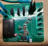
When applying mains power to the board, I get 115AC at J3 and J4. However, the LED doesn't light and I had trouble detecting any DC voltage at J11. The most obvious explanation in my mind is that I may have placed the LED backwards.
I read the previous posts on this thread regarding points to test for voltage. However, because none of the pins are marked it will take me a little time to research data sheets and identify test points. In the mean time I am going to order a few extra LED's as a back-up plan.
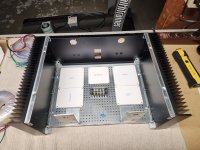
I posted a pic of my board although it may or may not provide useful information. I also posted a pic of my current enclosure mock-up with poster board footprints of my boards. (It's part of my obsessive-compulsive nature lol). I didn't post the schematic because it's at the beginning of this thread.
Thanks to X and Poseiden's Voice for hanging in there with me during my build.🙂
Respectfully. Dave M.
Just an update on my FH9HVX build.
The SFP soft-start board is the only one of my boards that isn't operating properly. (The other issue I had was a wiring error).
When applying mains power to the board, I get 115AC at J3 and J4. However, the LED doesn't light and I had trouble detecting any DC voltage at J11. The most obvious explanation in my mind is that I may have placed the LED backwards.
I read the previous posts on this thread regarding points to test for voltage. However, because none of the pins are marked it will take me a little time to research data sheets and identify test points. In the mean time I am going to order a few extra LED's as a back-up plan.
I posted a pic of my board although it may or may not provide useful information. I also posted a pic of my current enclosure mock-up with poster board footprints of my boards. (It's part of my obsessive-compulsive nature lol). I didn't post the schematic because it's at the beginning of this thread.
Thanks to X and Poseiden's Voice for hanging in there with me during my build.🙂
Respectfully. Dave M.
Attachments
Dave,
The other way to look at it is to make sure the anode of the LED (the long lead) is inserted into the hole closest to R5, which of course means that the cathode of the LED (short lead) would be in the other hole [which appears square in the PCB seen above].
Understand the phase configuration of the primaries of your Antek transformer. Each Antek toroid power transformer has dual primaries. Each RED colored cable on the transformer should be connected to J3 and J7 while the Black colored cables should be connected to J4 and J8. I see you have a terminal strip, so you want to be sure you connect your pair of Antek toroids properly. You can just connect the toroid primaries to the terminal strip and then have single wires from the terminal strip connect directly to J3,4,7 and 8 for ease of wiring and making sure it looks neat. If you want, use the same colored wires to avoid confusion. I would also twist any wire that is carrying AC primary voltage.
Please also flip the pcb over (like you did with the FH9HVX) and make sure all your soldering is neat and clean; it might take a little more heat/flux as these are thick boards. The assumption is you placed all the correct resistors in their proper locations! 😉
When you test the board, look at the schematic and notice all the areas that +5V DC should be present. Check those areas so you are convinced that all them are receiving +5V. Examples: Pin 1 of U2. Pin 8 of U3. Pin 3 of U4. Be careful with your multimeter. You don’t want the leads to accidentally slip and cause a short. Look at the schematic and the blank pcb you see above for hints and observe where the 5V supply trace travels on the pcb. Understand that the function of transistors U2, U3 and U4 depend on a properly functioning U1 (the black Meanwell IRM switcher).
DIY audio is all about testing subsystems and then putting the whole enchilada together.
Best,
Anand.
Last edited:
Hi X and Anand,
Thank you for your responses. I appreciate the opportunity to learn more about this rewarding activity.
My plan is to be slow and methodical with my testing. Especially, since this circuit involves components I am especially unfamiliar with. Thank you for your respective offers of advice. Dave M.
Thank you for your responses. I appreciate the opportunity to learn more about this rewarding activity.
My plan is to be slow and methodical with my testing. Especially, since this circuit involves components I am especially unfamiliar with. Thank you for your respective offers of advice. Dave M.
- Home
- Group Buys
- Soft as a Feather Pillow (SFP) SSR Soft Start Circuit GB