As important as power supplies are to a project...it's the least enjoyable part to me. Really excited about these SMPS developments!
Maybe I just leave this here,
I built (a variant of) another of Juma's lateral designs and run it with 4 laptop SMPS. Quite happy with the result.
I built (a variant of) another of Juma's lateral designs and run it with 4 laptop SMPS. Quite happy with the result.
These guys seem to have a rotating stock of SMPS
Electronic Components and Accessories | MPJA.COM
Not sure if I ever used them, but they must have come recommend at some point.
Electronic Components and Accessories | MPJA.COM
Not sure if I ever used them, but they must have come recommend at some point.
Yes Nelson Pass used MPJA power-brick SMPS's in the original Amp Camp Amp, the one where he taught people to solder while sitting outdoors at picnic tables.
Maybe I just leave this here,
I built (a variant of) another of Juma's lateral designs and run it with 4 laptop SMPS. Quite happy with the result.
I missed that post somehow. Well done, congrats !


I can’t find the post, but I believe Nelson once mentioned that stacking two SMPS to form a symmetric PSU may result in an audible beat between the two switching frequencies.
Any experiences in that sense?
No, but when I tested laptop SMPS bricks I saw that some of them have minus output node connected to safety earth so connecting two such PSUs in series would short-circuit one of them.
Disconnecting the minus node from safety earth is mandatory in that case.
Disconnecting the minus node from safety earth is mandatory in that case.
Last edited:
Has anyone tried Connex SMPS with class a amps, especially SMPS300RE | Connex Electronic which is available with +/-24V 300W and thus seemingly perfectly specified for firstwatt clones?
I can’t find many other smps with +/-24V and connecting two single rail smps together is said to confuse their voltage sensing, plus the safety earth issue mentioned above.
I can’t find many other smps with +/-24V and connecting two single rail smps together is said to confuse their voltage sensing, plus the safety earth issue mentioned above.
Not sure which one he was using, but Nick posted a couple of weeks ago, "I’ve used both Connex electronic and Micro-Audio. The former was not anywhere near as quiet as the latter."
Thank you for bringing up this topic. I am also very interested in SMPS for power amps.
I made a first try with SMPS on my Pass XO24-6 but I am not fully convinced.
I had quite a bit of residual 50Hz hum and its harmonics. This was audible when close to the speaker.
The linear PSU which I put together from simple LM317 based regulator was much better. Interestingly for me: The lin PSU benefitted a lot from connecting the transformer shield winding to saftey ground.
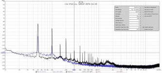
Attached is a sound card measurement (on the XO-24-6 low pass output) which shows the LM317 supply compared to a Meanwell APV-18. Also tried Meanwell IRM-60 which was slightly better but still much worse than the lin PSU. Adding additional RC elements to the SMPS output were only slightly better.
I made a first try with SMPS on my Pass XO24-6 but I am not fully convinced.
I had quite a bit of residual 50Hz hum and its harmonics. This was audible when close to the speaker.
The linear PSU which I put together from simple LM317 based regulator was much better. Interestingly for me: The lin PSU benefitted a lot from connecting the transformer shield winding to saftey ground.
Attached is a sound card measurement (on the XO-24-6 low pass output) which shows the LM317 supply compared to a Meanwell APV-18. Also tried Meanwell IRM-60 which was slightly better but still much worse than the lin PSU. Adding additional RC elements to the SMPS output were only slightly better.
Attachments


This is my 2nd ClassA amp powered by SMPS.
My M2x picks up hums easily from a nearby trafo previously, and there are many ways to reduce the effect by using Mumetal shielding. The other problem is the ground looping noise that I struggled with this amp.
After swapping to SMPS, all the above issues are gone for good, now it super quiet, no hums, no hisses. Time to enjoy this amp after a long tinkering effort! Now no longer need any MuMetal shield.
This smps powered up a total of 264mF of capacitor bank every time without a sweat!
I have never been happier with this PS setup.
Nice build meanie!
Which SMPS are you using?
Is the big cap bank required? Have you tried without it?
I thought a SMPS does not need or even does not like a lot of capacitance on the output.
Which SMPS are you using?
Is the big cap bank required? Have you tried without it?
I thought a SMPS does not need or even does not like a lot of capacitance on the output.
I got mine from Micro-Audio. Great support he provides.
I did power up the ClassA amps without cap bank at first, they were totally quiet already!
Then i put in 60,000uF for my F6, and i love it.
This M2X got 264,000uF, not a must, but since i got the Universal PS board hanging around, so i used it.
You may run it thru using some smps filter circuit if that makes you feel better, but i won't do it till I see bad critters in my supply rails when i got the time to check. I ran out of capacitors trying to trip this SMPS to go into failsafe mode, it just powers up smoothly without any hiccups.
Last edited:
With the ability to power up that much capacitance, you could try separate filter banks for each channel. Might as well go for improved stereo separation + imaging.
Fantastic build Meanie! Looks great and I’m sure it sounds sweet also.
I’ve got a similar project in the works that will use the same SMPS but different M2 boards.

I’ve got a similar project in the works that will use the same SMPS but different M2 boards.
The ripple and other noises vary among the products out there.
Of the ones I've tried so far the best luck has been with Meanwell and Triad.
If the supply rejection of the circuit is good, you can often get away with just
a simple cap to ground on the rail, but if the noise is higher and/or the psrr is
not good, then a filter is necessary.
This is fine, but there are usually limits to what a switcher will start up into.
If the circuit draw is initially high as with a big bank of caps, many switchers
will go into protect mode.
With the P ch version of the DIY VFET, we did well with a Meanwell 36 volt
switcher and a simple L/C input filter. The N channel version has a lower psrr
and needed more filtering, ending up with a relatively large R/C network for
each channel. It loses a little supply voltage, but the circuit worked as well
as the L/C and filtered down to below 120 Hz.
I've been experimenting with the idea of inserting a specially optimized Darlington capacitance multiplier, between the SMPS and an enormously large bank of electrolytic capacitors.
The voltage waveform at the input of the Darlington is filtered by a simple RC lowpass, so it's a rising exponential
The fourth row attempts to carve out a bit of safety margin, by assuming a higher than normal SMPS output voltage and a lower than normal SMPS "hiccup mode" threshold. The math says 0.2 sec, so be conservative and choose an R*C timeconstant significantly longer, such as 0.5 sec or even more.
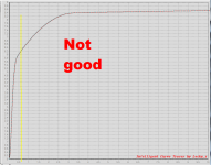
Clearly for such large timeconstants we'll need large values of Rbase . . . and that's why I'v chosen a Darlington arrangement -- Darlingtons need very little base current so they can operate with very large base resistors. Yes you lose two diode drops going thru a Darlington. And that's in the best case scenario, where the input transistor operates at a VCE of only 0.6V, while the output transistor operates at a VCE of only 1.2V. Plenty of transistors defecate the bedsheets at these low values of VCE, so measure them beforehand and choose wisely.
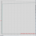
Here's what a good candidate looks like. VCE on the horizontal axis, ICE in milliamps on the vertical axis. Notice that it behaves nicely even below VCE=0.6 volts.
Finally, remember that at the instant of switch-on, the Darlington will have 36V across it while it conducts 4.2 amperes. That's an instantaneous power dissipation of 151 watts. It will be very important to study the SOA curves, and also to select a suitable heatsink!
_
The voltage waveform at the input of the Darlington is filtered by a simple RC lowpass, so it's a rising exponential
- Vbase = Vsmps * {1 - exp[-t / (Rbase*Cbase) ] }
- Icharge_caps = Cenormous * dV/dt . . . . and must be <= Imax_smps
- dV/dt = dVbase/dt = Vsmps / (Rbase*Cbase)
- Imax_smps >= Cenormous * Vsmps / (Rbase*Cbase)
Code:
Vsmps    Imax_smps    Cenormous   (Rbase * Cbase)
=================================================
 36 V       4.2 A       3300 uF      0.03 sec
 36 V       4.2 A      22000 uF      0.20 sec
 36 V       4.2 A     115000 uF      1.0  sec
 38 V       3.9 A      20000 uF      0.195 sec
The fourth row attempts to carve out a bit of safety margin, by assuming a higher than normal SMPS output voltage and a lower than normal SMPS "hiccup mode" threshold. The math says 0.2 sec, so be conservative and choose an R*C timeconstant significantly longer, such as 0.5 sec or even more.
Clearly for such large timeconstants we'll need large values of Rbase . . . and that's why I'v chosen a Darlington arrangement -- Darlingtons need very little base current so they can operate with very large base resistors. Yes you lose two diode drops going thru a Darlington. And that's in the best case scenario, where the input transistor operates at a VCE of only 0.6V, while the output transistor operates at a VCE of only 1.2V. Plenty of transistors defecate the bedsheets at these low values of VCE, so measure them beforehand and choose wisely.
Here's what a good candidate looks like. VCE on the horizontal axis, ICE in milliamps on the vertical axis. Notice that it behaves nicely even below VCE=0.6 volts.
Finally, remember that at the instant of switch-on, the Darlington will have 36V across it while it conducts 4.2 amperes. That's an instantaneous power dissipation of 151 watts. It will be very important to study the SOA curves, and also to select a suitable heatsink!
_
Attachments
Fantastic build Meanie! Looks great and I’m sure it sounds sweet also.
I’ve got a similar project in the works that will use the same SMPS but different M2 boards.
Thanks Vunce!
Would love to see your M2 in action with the SMPS too.
- Home
- Amplifiers
- Pass Labs
- SMPS powered small cl. A amp