Jan,
Can you tell me at the output of positive side boost converter why you tapped the diode pad instead of the more silent capacitor pad?
OK, I don't want to be too strict, for a first switch mode project this is very good layout. But rev1.0 will definitely will be free form such minor mistakes won't it?
I can measure up to 70MHz and don't see anything. I do see something from USB chargers but don't see that at the output of SilentSwitcher.
Jan
I believe this. But the resonances start above 70 MHz, and what you told about pure sinewave was about "the ripple of some of the latest converters", not the additionally LC filtered and linearly regulated residual.
If you measure on the linear output with a 70 MHz analog scope, then you can't trigger to the switching event, therefore it will be asynchronous, and because of averaging of the many different sweeps no signal can be observed even if there is switching noise.
You need a trigger source (for example the output of the DC/DC converter), a faster scope, and probably a HF amplifier, and a proper cable (1:10 probes are not capable for this purpose) to make relevant measurements about HF noise.
Is "the ripple of some of the latest converters of 1 mV of pure sinewave" apply to your boost converter also? At which point? Before or after the additional LC filter?
I agree with your choice: the additional LC filter is useful. But checking the result in reality with proper measurement techniques is more reliable than simply trusting some rough approximations. And layout iteration based on measurements can lead to a better design.
I agree with your choice: the additional LC filter is useful. But checking the result in reality with proper measurement techniques is more reliable than simply trusting some rough approximations. And layout iteration based on measurements can lead to a better design.
i'm working on an low power LLC design (dc-dc) with a PWM mode with a short to neutral switch. the signal looks like a biphasic PW modulated signal with fixed freq. it can be synced to a wordclock. Im using a ferroxcube gapped ferrite toroid, normally developed for classD output filtering. plus some LDO burning off to regulate. prim-sec coupling is about 2pf as the windings are sectorial, and the leakage inductance is used for the LLC.
I don't think we are discussing AC-DC converters here. My SilentSwitcher runs on a USB charger, a PowerBank or a (LiPo) battery.
Look at the noise graph. The vertical scale is uV.....
Jan
Nice indeed!! Is there output impedance measurements also? And please make your measurement go to at least 200k.
//
Last edited:
Nice indeed!! Is there output impedance measurements also? And please make your measurement go to at least 200k.
//
Yes, it is in the Kickstarter write-up:
https://www.kickstarter.com/projects/1684029908/the-silentswitcher-mains-free-low-noise-15v-and-5v
You need to scroll down a bit.
Jan
i'm working on an low power LLC design (dc-dc) with a PWM mode with a short to neutral switch. the signal looks like a biphasic PW modulated signal with fixed freq. it can be synced to a wordclock. Im using a ferroxcube gapped ferrite toroid, normally developed for classD output filtering. plus some LDO burning off to regulate. prim-sec coupling is about 2pf as the windings are sectorial, and the leakage inductance is used for the LLC.
LLC is definitely a good start for low CM noise.
Is it soft switching in the full pulse width control domain? What is the freq? How much you can control output voltage?
I start with a bitclock of 64x96khz, divide that down to 32x96k and transmit that to the isolated side. there the 32*96 is divided down again to restore symmetry lost in the digital coupler and that is the shortest pulse width. the switching freq is 4x96 khz at max 100% PWM i decided to use onlty discrete PWM steps for simplicity to get a crude voltage control, and to have the PWM harmonics at known positions. I added a 1.5 pulse width control, so have steps at 1.5 2.5 and 4x minimum pulse width, that showed a decent volage range. this idea is to tap off the raw dc off a power amp rail to create a clean low voltage for a DSP board or the like (like the nanodsp where I put the hooks in) at startup the system has to start freerunning, then locks onto the clock from the dsp board. i'm currently programming a silego slg46620 to do all the control stuff. just add a silabs isolated gate driver. fdd1600 is the switcher. planned input voltage range is 24 to 100V. for 5-10V out, the rest it linearly burned away. i have a ltspice file if you like to play with it.. just recently found articles about neutral point switching LLC. i was not alone .. LLC tuning is always working at the freq of minimum load dependency ..
Thanks! What is the switching like at small duty cycle? I dont understand yet how could it be ZPS.
Jan,
Can you tell me at the output of positive side boost converter why you tapped the diode pad instead of the more silent capacitor pad?
OK, I don't want to be too strict, for a first switch mode project this is very good layout. But rev1.0 will definitely will be free form such minor mistakes won't it?
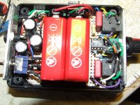
Even better taken a tiny distance away from the capacitor pad outside of the switching loop, it is total control of this switching loop that is the main skill in doing SMPS layout. Depending on the controller I like to see the 0V (GND) part of the two switching loops as a separate ground pour on the same side as the components, joined at a single point usually at the controllers thermal pad.
One thing to watch is power drawn, you don't want to use an SMPS at its minimum power levels, they go into what I call chirp mode and can become very noisy in the audio frequency range (around 8KHz).
The attached shows the switching loops rather nicely and also some of the more advanced SMPS layout techniques.
More than anything bad layout is a cause of SMPS noise and their bad reputation, I have just had to re-layout a complete board with 3 high power LED driving SMPS's because it was failing EMC, the layout was done by a PCB contractor and was a disgrace. What I can say is Jan has spent some time on this layout and it is better than some done by so called professionals!
Attachments
Even better taken a tiny distance away from the capacitor pad outside of the switching loop, it is total control of this switching loop that is the main skill in doing SMPS layout.
Telling keep distance is quite confusing since galvanic connection is required. Distance between what objects? What "is total control of this switching loop"? I can't insert any object from the previous parts in place of "it" to make the sentence meaningful.
If you mean the output track should go on a route where the least HF flux is surrounded by output loop, then I agree. However I couldn't read your sentence this way.
Depending on the controller I like to see the 0V (GND) part of the two switching loops as a separate ground pour on the same side as the components, joined at a single point usually at the controllers thermal pad.
One thing to watch is power drawn, you don't want to use an SMPS at its minimum power levels, they go into what I call chirp mode and can become very noisy in the audio frequency range (around 8KHz).
It is called burst mode or cycle-skipping mode by manufacturers.
The attached shows the switching loops rather nicely and also some of the more advanced SMPS layout techniques.
More than anything bad layout is a cause of SMPS noise and their bad reputation,
Omitting CM filter completely from offline converter is not less harmful... ;-)
What I can say is Jan has spent some time on this layout and it is better than some done by so called professionals!
I agree.
Here is an article about difference of Linear and Switch-mode power supplies for newbie's reference.
Here is an article about difference of Linear and Switch-mode power supplies for newbie's reference.
I think that article is about 20 years out of date. SMPS's are much different today, much much better in almost all aspects, mostly driven by tablet and cell phone requirements.
BTW Am I the only one finding the name 'linear supply' for a transformer and rectifier somewhat amusing? 😉
Jan
Yeah, total brain fart. Better called LFSMPSWALOI -- Low Frequency SMPS Wasting A Lot Of Iron.
Did you see my PN, Jan?
Did you see my PN, Jan?
I think that article is about 20 years out of date. SMPS's are much different today, much much better in almost all aspects, mostly driven by tablet and cell phone requirements.
I haven't read it yet, but basic principles stays the same. Many theories and techniques about ClassD audio were developed 40 years ago in connection with motor drives. And today that things are reinvented.
BTW Am I the only one finding the name 'linear supply' for a transformer and rectifier somewhat amusing? 😉
I try to avoid using this faulty term also, and not a long time ago I mentioned it is not linear. Only stabilizer is what linear.
Telling keep distance is quite confusing since galvanic connection is required. Distance between what objects? What "is total control of this switching loop"? I can't insert any object from the previous parts in place of "it" to make the sentence meaningful.
If you mean the output track should go on a route where the least HF flux is surrounded by output loop, then I agree. However I couldn't read your sentence this way.
.
Yes feedback should be taken from outside of the switching loops, I have always been taught to that the switching loops are AC, the DC doesn't start until after the output cap, so feedback should be taken outside the switching loops, or from the load in some instances if there is some distance between the supply and the load, more applicable to charging supplies where you want a specific voltage at the load.
Total control of the switching loops is doing the correct layout so you know exactly where the high current is flowing.
It is nice to see SMPS's promoted and getting some good press and interest in DIY audio...
🙂
http://www.ti.com/lit/ds/symlink/lm20343.pdf
Page 21 Item 4 is what I was referring too.
Page 22 has a nice picture of the loops, these loops are applicable to linear supplies as well, though not as critical as switchers its still worth the effort during layout.
Page 21 Item 4 is what I was referring too.
Page 22 has a nice picture of the loops, these loops are applicable to linear supplies as well, though not as critical as switchers its still worth the effort during layout.
I think that article is about 20 years out of date. SMPS's are much different today, much much better in almost all aspects, mostly driven by tablet and cell phone requirements. Jan
I couldn't agree with you more. I just completed a headphone preamp, & testet it with a 24v/1A /SMPS which splitted to +/- 12v using a TLE2426 v.earth circuit. I was indeed very pleasantly surprised by both the noise and the accuracy compared to the batteries. Almost precise +12.003/- 12.004 volts on the rails and virtually no dc off-sett at op-amp outputs what so ever. Perhaps I've been lucky with the SMPS I bought!
Attachments

Maybe I am old fashioned but why use small SMPS for low power devices when "linear" PSU's can be used ? Ripple, noise etc. of SMPS might all have improved but how about longevity ?
I repair more SMPS than I like. Apparently the high frequencies shorten the lives of caps and semis. With "linear" PSU's one only needs to replace electrolytic caps after 10+ years. IMHO modern LDO's perform quite OK and losses can be made minimal but of course their efficiency is not as good as with SMPS. Also many SMPS radiate garbage that affects other equipment. I am now testing a commercial device that has a tiny switched PSU that manages to disturb my amplifier big time. Its replacement will be a linear PSU as power draw is very low with 6V @ 0.3A.
As good as modern SMPS chips may be, it still is quite hard to build them DIY and have optimal results as many lack the equipment to measure them. They will also be more expensive to build. Mains connected SMPS are out of the question for DIY in contrary to mains connected "linear" PSU's. The chinese Ebay SMPS PCBs all lack something and are only made to be cheap. Ready made SMPS that are delivered with equipment often have problems. I dare to state that in general SMPS that are delivered with audio equipment are often mediocre performers that are easily bettered by classic "linear" PSU's. Classic "linear" PSU's can be switched off completely from mains with a real power switch in contrast to several chargers that are always connected to mains which I simply do not like. When looking at the cable and adapter clutter in my audio corner in the house I really prefer to have devices with built in PSU's. Simplified this has led me to thinking I better avoid ready made SMPS for low power devices and audio specifically.
Of course I see the design Jan Didden made as a very nice alternative but if I need a cheap chinese power bank driving it I have some doubts. Again cheap LiPo batteries and a crappy charger needed 😉 The other option is to use a "standard" 5V 2.1A SMPS. Point is I have thrown away many a "standard" 5V 2.1A USB charger as many are very noisy and mains polluting. Feeding a Silentswitcher with a classic "linear" PSU seems counterproductive 😉 I will try one out of course as I am always open to change and improvement.
True challenge would be to design a mains fed so 115V/230V AC input SMPS with very low radiation/EMI, very low ripple and noise, high efficiency and high reliability. It could serve as building block for many audio devices with superior characteristics to the original SMPS. I am pretty sure that would be more expensive than the classic PSU's but then it would make sense for me. The world will not be better with even more battery use than we already do. Mains fed with ultra low conversion losses is the cheapest way and environmentally also a better choice (with the big picture in mind).
Last edited:
- Status
- Not open for further replies.
- Home
- Amplifiers
- Power Supplies
- SMPS for small signal analog circuits