Hmmmm indeed ... this is the "interesting" zone of audio playback that I have referred to a number of times - personally, I can't go down the 'coloured' route, because part of me will always be aware that a compromise has been made which has lost part of the sound. The technically more correct solution is harder work to make satisfying, I will grant that, but in my world this is because it's shining a stronger light on the sound world that's being projected by the system - the wrinkles and marks on the skin are more obvious.I'm thinking now of power amps rather than the small signal stuff but in the past I haven't really enjoyed listening experiences from any of the amps I have owned that have been supposedly of above average technical performance. I think I tend to prefer the more "coloured" and "colourful" sound some set ups produce. To me, they can be the setups that provide listening satisfaction long term and with a wide variety of quality of source.
Many favour the "wire with gain" approach, I just find it only shone with a few select recordings...
Hmmm 😀
So why would I take this "harder" route? Because, I've heard what the "superior" system is capable of doing when all the stars are in alignment, this is truly the good stuff!! Yes, it's the no pain, no gain mantra I'm afraid - once heard, never forgotten is completely convincing, overwhelming sound, so this will remain my destination point as long as I'm in this game ...
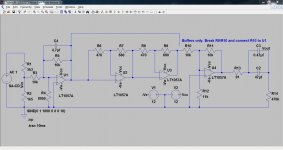
This is the circuit.
There are four opamps. Opamp type for this test was the TLE2072. The first and the last are the common buffers which were in place place for both tests. These were configured as inverting stages which have a reputation for performing better in certain circumstances. R4 and R12 are the two "unique" components which "throw away" a little of the open loop gain at the expense of increasing distortion and noise.
The two non inverting buffers use the same technique with R6 and R8 having the effect of "throwing away" some of the open loop gain. The connection between R9 and R10 was broken to allow either configuration to be tested.
This technique of increasing the noise gain is used by manufacturers to enable the distortion of opamps to be measured. Without this technique the distortion can be below measurable limits. The big question for audio is whether or not it has advantages for sonics. Some designers believe it does because it enables the opamp to have more stability, whereas even unity gain stable opamps used with 100% nfb are running right on the verge of instability.... and I'm trying to find out where the truth might be. And I have absolutely no idea what might be the sweet spot for doing this. There is huge possibility in the choice of resistor values that can be used.
Attachments
Hmmmm indeed ... this is the "interesting" zone of audio playback that I have referred to a number of times - personally, I can't go down the 'coloured' route, because part of me will always be aware that a compromise has been made which has lost part of the sound. The technically more correct solution is harder work to make satisfying, I will grant that, but in my world this is because it's shining a stronger light on the sound world that's being projected by the system - the wrinkles and marks on the skin are more obvious.
So why would I take this "harder" route? Because, I've heard what the "superior" system is capable of doing when all the stars are in alignment, this is truly the good stuff!! Yes, it's the no pain, no gain mantra I'm afraid - once heard, never forgotten is completely convincing, overwhelming sound, so this will remain my destination point as long as I'm in this game ...
Hmmmmmmm 😀
I do understand, really I do 🙂 This is getting to why the "one size fits all" doesn't perhaps work... we all look or listen for different things.
I wonder (well I know) how DAB, that's our digital radio system, would sound through ever more technically correct solutions. I look for a balanced system that shines with pretty much anything.... horses for courses...
Hmmm....
This is the circuit...........
Thanks Mooly can you decode your schematic to which AAA and BBB files.
Last edited:
Yes, aaa was the full path from left to right with all four stages in circuit as drawn. bbb was just U1 as the input buffer and U4 as the output buffer. For this the circuit was broken at the point where R9 and R10 join and the left hand side of R10 connected directly to U1 output.
You will not get anything from these tests, only difference - yes/no. To evaluate such subtle changes reliably you need perfect recording chain, 24 bit and not 16 bit, and you need to evaluate it with perfect DAC, not with iphones, iPads or soundchips on motherboard. It is nice you have replies, but there is no usable output from these preference tests. Even standard measurements would say more.
You will not get anything from these tests, only difference - yes/no. To evaluate such subtle changes reliably you need perfect recording chain, 24 bit and not 16 bit, and you need to evaluate it with perfect DAC, not with iphones, iPads or soundchips on motherboard. It is nice you have replies, but there is no usable output from these preference tests. Even standard measurements would say more.
Perhaps... although I find the information has been useful. I would have thought if a circuit under test were "characterless" then it would remain so in 24 or 16 bit. Or am I missing something there 🙂 The differences that quite a few listeners pick out are ascribable to the recognised traits of the active components used.
Its all been hugely interesting and enjoyable running these tests though.
Much can be accomplished with 16bits. But yes, only differences yes/no at this level of testing are possible.
Mooly,
What differences are apparent in simulated results?
Wave file may be used as stimulus for simulation, and results captured in wave file. It can be very time consuming. I've done this before, using both MLS and swept sine to recover IR of simulated circuits.
Going for perfect high score is a game. Statistically relevant results are readily obtainable without perfect score. Getting 5/5, 7/7 is very good indicator of difference, and build confidence in test subject. To observer with any statistical knowledge, 20/20, 100/100 looks mighty suspicious.
Extended sampling statistics of individuals over series of trials should show a distribution. If lots of perfect scores show up, then there are obvious differences in test cases.
In these tests, measurable differences are all so small that repeated and extended listening is required just to get a significant yes/no result.
Mooly thanks, good test it showed difference even if could be better with 24bit as sugested, my afterwards thinking is that it could have been extended with third CCC file where two middle buffers had been 100% nfb configured.
I really used LTspice more as a means of drawing rather than anything else. I haven't run any real simulated runs on it but it could be interesting as a comparison to see the effect of the resistor as values change. If I get time later I will. It would be interesting to see how distortion increase.
My experience of opamps in LTspice has been that they come nowhere near real behaviour of the real parts although that was when I was trying the CFB opamps.
Even with Pavels far more meticulously run tests and better hardware the differences are still apparent in the ABX test. I think there is validity in all this.
When I do an ABX I sometimes get a run of 00/xx where it seems I hear a difference but for some reason pick the wrong file everytime. I find ABX tests mentally tiring tbh.
Mooly thanks, good test it showed difference even if could be better with 24bit as sugested, my afterwards thinking is that it could have been extended with third CCC file where two middle buffers had been 100% nfb configured.
That could be worth a go 🙂
I may well just do that (but not today 🙂) and perhaps using an LM4562 as the opamp for all this time.
Jay, hat off for your FET prediction.
😀
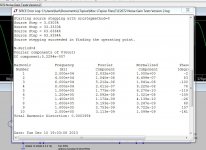
OK, here's what LTspice makes of the distortion for the whole chain and then with all the "noise gain" resistors decreased to 100 ohm. And this is at 20kHz and 2 volts RMS output. Trouble is, I don't believe it 🙂
Attachments

😀
OK, here's what LTspice makes of the distortion for the whole chain and then with all the "noise gain" resistors decreased to 100 ohm. And this is at 20kHz and 2 volts RMS output. Trouble is, I don't believe it 🙂
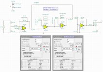
Nice specs you get, i try set your schematic up in freware "TINA" from Texas Instruments to compare with your simu and then get back.
To defend simu little, here some things to consider simu verse real world:
Standard source used in simu is 0R z out and pretty nicer than real world, unless you set up complicated nets for simu the real world source you have and also complicated net for the cable used.
Standard load is nothing or a nice resistor without cable and pretty nicer than real World, unless you set up complicated nets for simu the real world load you have and also complicated net for the cable used.
Layout in simu doesn't matter as in real world where clever thinking needed, unless you set up complicated nets for simu the real world layout.
By the way Jay seemed pretty positive with your files this time, has not mentioned fatigueing 😀.
Last edited:
Simulating behaviour of opamps in LTspice or any other software is useless, because the models aren't accurate, or detailed enough - GIGO. There are just a couple of models freely available which truly reflect what's inside the chip - discrete models, with every transistor included - but these are for obsolete devices. Do you think the makers of the latest and best opamps are going to give away all the 'magic' little details that make their chips work 'better', 🙂?
Using these precise models does show interesting behaviour - for example, PSR is not straightforward, easily predictable - changing gain alters the characteristics quite strongly.
Using these precise models does show interesting behaviour - for example, PSR is not straightforward, easily predictable - changing gain alters the characteristics quite strongly.
Jay, hat off for your FET prediction.
No, I didn't try to predict anything. Instead I tried to describe the sound (using language that can be universal or not). What important is the sound description because the difference is OBVIOUS to my ears/brain. My prediction on the other hand will be LIMITED by my knowledge and experience. If my prediction wrong, such as AAA came out direct, people might draw a wrong conclusion by throwing all the data, they might not have the understanding that yes there is a possibility that AAA is direct.
My experience of opamps in LTspice has been that they come nowhere near real behaviour of the real parts although that was when I was trying the CFB opamps.
I have mentioned in threads related to LTSpice or amp design how I use LTSpice.
I build many amps and I can here differences. So what I need is any variable within LTSpice simulation that has correlation with what I hear. Such THD log shown here has no correlation.
There is correlation tho, in the FFT plot drawn with certain parameters (han windowing, sample size, etc). Even by plotting simultaneously several input of close amplitudes (where you can see the "linearity" of distortion).
From my limited experience listening to opamps and correlating them with FFT, the correlation was "perfect". That's why I was curious to see the pomegranate in LTSpice (but my computer is broken right now) to see what I have heard.
Last edited:
By the way Jay seemed pretty positive with your files this time, has not mentioned fatigueing 😀.
No, there isn't issue with fatigue. Only less critical fatigue types:
1) AAA is flatty "boring" like Frank said. Sometimes I put this kind of perception into fatigue as well.
2) BBB can be fatiguing as a result of its transparency, if the proceeding signal is fatiguing. Higher dynamic range can bring driver's cone displacement to reach it's problematic/critical displacement, so any kind of limitings can give positive perception.
If only I listened through one speaker, and it was that "unique" speaker, I would have had difficulty to choose which file is better (that's why originally I mentioned the files were "equal", that was when I used that "unique" speaker before changing to other speakers). Because the vocal from AAA really show it's charm, and the music was more relaxed because of the smoothness.
But after using the other two speakers I knew that with most speakers (including my other two designs), that beauty might not be revealed.
As I said, differentiating these two files was harder than differentiating the previous test files. With previous files I only need to play one file a minute or so then change to the other file and I could hear the difference. For these last files I need more effort (this old trick can be used in ABX too). I played one file in a loop (5 or 6 times) until my ears get accustomed to the sound, then I change the file and my ears/brain will suddenly hear differences.
And because I found this was harder than before, so I brought my Sennheiser to work (I don't have computer or Foobar at home). But I had to find the critical segment in the music (it was the 0:20:00) for me to be able to get zero mistake.
But I still had the confidence in my ABX to push only 2 buttons to decide which one is which. For example, first I pushed the A button and I knew it was the BBB. Then I pushed X and I knew it was AAA, so I pushed A=Y (or B=X).
Mooly here is distortion simu from program TINA with schematic as post #82, 7,07V RMS input 1KHz and 20KHz, output no load 2V RMS.
I rarely work with preamp circuits. But I don't understand why Mooly chose such a high load impedance (470kHz)? Imagine if the preamp has to drive 3 VSSA amps in parallel (for multi amping)!
Okay, it's the buffer. But may be difficult load matters?
- Status
- Not open for further replies.
- Home
- General Interest
- Everything Else
- Small Signal Listening Comparison Test