Hi guys I would like to use Transformer Input for the amplifier with impedance of 22kohm so what should be my primary resistance and secondary resistance.
Reason for transformer input is for its distinct tone that many like. Rupert Neve uses transformer input.
How to calculate the primary and secondary resistance.
Reason for transformer input is for its distinct tone that many like. Rupert Neve uses transformer input.
How to calculate the primary and secondary resistance.
Rhythmsandy, not certain why you are mentioning resistance figures. Do you mean the DC resistances of the windings? Transformers perform various functions according to the particular application. Microphone transformers transform the impedance of the microphone, maybe 200 Ohms to a much higher value that allows the first stage of the preamp to exhibit its best noise performance. What this value is depends on the active devices in the first stage eg valve, FET, Bipolar transistor etc.
What you are going need is a 1:1 ratio bridging transformer, perhaps described as 20K primary 20K secondary. The 22k input impedance of your amplifier will remain at this value looking into the primary but will now be floating balanced. Good transformers don't come cheaply and have Mumetal (nickel/iron) cores and often a triple mumetal shield around them to keep out stray magnetic fields. The better ones also have an electrostatic shield between primary and secondary. The windings are often in the form of "pies" meaning they are segmented rather than jumble wound.
Next we come to the most important attribute, which is the inductance values of the windings. The Archilles Heal of audio transformers is low frequencies and high levels. We need to have sufficient inductance so that at (say) 20 Hz the inductive reactance is not appreciably shunting the system impedance (20K) Ultimately lack of inductance can result in core saturation and distortion.
Not many manufacturers quote winding inductances but I recall seeing a figure of 30 Henrys for a certain model of German Bayer microphone transformer. You need to work out the maximum input level in dBu that your amplifier is going to see when driven to full output. Have a look at the transformer specs to see if they quote distortion figures at 20 or 30 Hz for this level or higher.
Keith
Now that you have given out some homework/self help guidance, I suspect the need for transformer coupling will disappear.
Ha , ha - math makes em' run !! 😀
The only input trafo I used was one from RS (isolation trafo).
Kieth is right ,it's rated to 40hz - low bass suffered.
I fixed my system ground loop - goodbye trafo.
OS
The only input trafo I used was one from RS (isolation trafo).
Kieth is right ,it's rated to 40hz - low bass suffered.
I fixed my system ground loop - goodbye trafo.
OS
Transformer theory yikes!
Place one in a multiple stage design with gobs of global feedback and watch noobs chase oscillations all day 🙂
I haven't followed this thread in a long time and in fact don't remember the final version i built, I need to open the map up and look at the boards but this "Spooky Leech" version has me intrigued.
Attaching the Symasui IPS to Vzaichenko NS OPS i see that servo function is strange.
Offset start from 3v and ended at 2.9mV.
This give me the opportunity to try a non servo symasui version.
What i found?
Offset in non servo version is 2.9mV!
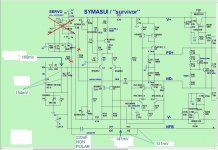
This Symasui survivor IPS perform far better without servo!
This was tested to Slewmaster OPS too.
Here is the non servo Symasui Survivor on the Slewmaster OPS.
Offset start from 3v and ended at 2.9mV.
This give me the opportunity to try a non servo symasui version.
What i found?
Offset in non servo version is 2.9mV!
This Symasui survivor IPS perform far better without servo!
This was tested to Slewmaster OPS too.
Here is the non servo Symasui Survivor on the Slewmaster OPS.
Attachments


Last edited:
Symasui Survivor+Slewmaster no servo
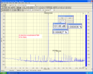
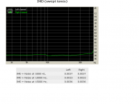
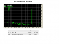
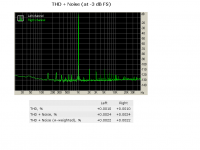
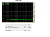
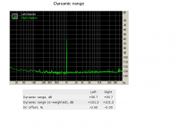
Using RMAA.
Using RMAA.
Attachments


Hi Pete.
I am a bit late, but that are really good news- i thought it falls a wall of stones down.....
Your Mongrel thread gives me motivation to learn more in audio amplification- and it
keeps on hard and slowly- but learning.
Here are many other members with different stuff.
I will follow your new inspired ideas even though i have not fully finished the great 2OPS
Slew Amp with any IPS configuration- that is a bit...... but winter is coming.....
Regards
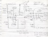
Symasui Survivor new servo like Onkyo
1)The new servo circuit.
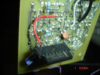
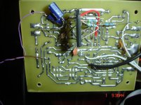
2+3)Not beautiful but functional🙂
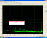
4)The settling time of the TL072 servo circuit.
5)The settling time of the LF 412 servo circuit.
6)The settling time of the New NJM2068Lservo circuit.
7)The original servo circuit on an Onkyo A8057 Service Manual.
1)The new servo circuit.
2+3)Not beautiful but functional🙂
4)The settling time of the TL072 servo circuit.
5)The settling time of the LF 412 servo circuit.
6)The settling time of the New NJM2068Lservo circuit.
7)The original servo circuit on an Onkyo A8057 Service Manual.
Attachments


Last edited:
Testing the new servo
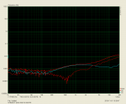
Testing using steps,this is the most suitable test for servo testing(my opinion).
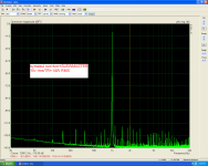
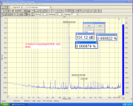
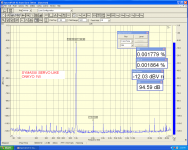
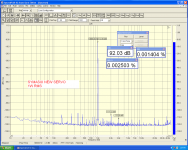
Testing using ARTA to see distortion in other frecquencies than 1KHz.
The last picture is from the first symasui servo using 1M,1M 1uf 1uf
Much better in low frequencies but i see a little jump in the 1khz area.Waiting for recommendations.
Testing using steps,this is the most suitable test for servo testing(my opinion).
Testing using ARTA to see distortion in other frecquencies than 1KHz.
The last picture is from the first symasui servo using 1M,1M 1uf 1uf
Much better in low frequencies but i see a little jump in the 1khz area.Waiting for recommendations.
Attachments
-
 SYMASUI 1W 2068 SPECTRA.PNG123.9 KB · Views: 192
 -
 1W SPECTRA.PNG125.2 KB · Views: 191
 -
 LIKE ONKYO 14V 20KHZ.PNG103.8 KB · Views: 534
 -
 20KHZ 14 V.PNG105.2 KB · Views: 543
 -
 20V NJM 2068 STEPS.PNG64.4 KB · Views: 558
 -
 symasuy 14v onkyo like steps.PNG75.6 KB · Views: 561
 -
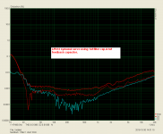
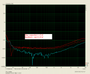 filter 1.47 feedback 0.47 lf412.PNG67.9 KB · Views: 568
 -
 1.1 steps.PNG69.4 KB · Views: 208
Last edited:
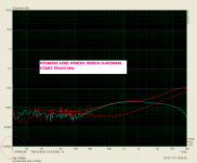
Why does the start up step to nearly 4V offset?
It should not do that.
The inherent offset is near zero without the servo.
It should not do that.
The inherent offset is near zero without the servo.
See post#9570 picture 6.Why does the start up step to nearly 4V offset?
It should not do that.
The inherent offset is near zero without the servo.
New offset circuit gives 2V only and settling time for zero offset=3''
it should not do that.
2000mVdc of start up offset is ridiculous !
especially when no servo is one hundred times better than with servo.
2000mVdc of start up offset is ridiculous !
especially when no servo is one hundred times better than with servo.
What you believe that is the turn on "bump" in all amplifiers without protection-delay circuits in the output?it should not do that.
2000mVdc of start up offset is ridiculous !
especially when no servo is one hundred times better than with servo.
but I thought you said way back that without the servo the start up offset was very low.
Is that what you said?
Is that what you said?
The issue with longer settling is not the OpAmp, but the values around it.
LF412 is far better than NJM2068L.
LF412 is far better than NJM2068L.
Sure ,but i believe that is the topologi, not the values around LF412.The issue with longer settling is not the OpAmp, but the values around it.
LF412 is far better than NJM2068L.
There isn't the long settling time only,please see Steps closer😉
I have play with the values around LF412 before without success.
If you have a better option i will follow🙂
May be Ostripper will come with a better solution.

I have chosen the NJM2068 because that is i have on my hand and because i wanted to do this without cutting traces.
Last edited:
(Below) is one design that I really wanted to try.
Maybe with a classic simple EF3 (true single pair toshiba/ sanken 70W OPS
(HK680 like).
Non modular full project with the standard compound Vbe "sandwiched"
between the driver pair.
An advanced cool running CFA. This input stage is mostly 12V @ <10ma per rail
operating current. Most beautiful "soft clip" at the VAS , as well.
It simulates way better than CFA-X or any prior models. Some might just
need a smaller (<100w) refined design.
BTW - I still like spooky .... but this is a unique design with many advantages.
OS
I am very happy for you and great your mind is still kicking, too, with new things to try.
🙂
-Richard
- Home
- Amplifiers
- Solid State
- Slewmaster - CFA vs. VFA "Rumble"