Hi
I am on completing CFA XH 1.3 BOM to populate my board. Could you advise me Voltage rating for 1000uf cap C7 and C8? I will use 50V rail. In jwilhelm capa Bom he indicated 50V....
That's on the 12V end of the input board. 50V will be fine. If I remember correctly these boards had limited space for that cap so it was hard to fit a 100V cap there, otherwise I would have used one.
That's on the 12V end of the input board. 50V will be fine. If I remember correctly these boards had limited space for that cap so it was hard to fit a 100V cap there, otherwise I would have used one.
I had in mind i could use lower voltage rating since ithey was at 12V end (same as VSSA) but i am wrong. Even in 50V it's difficult to find 5-13mm model in good brand many are 7.5-16mm....
Marc
I had in mind i could use lower voltage rating since ithey was at 12V end (same as VSSA) but i am wrong. Even in 50V it's difficult to find 5-13mm model in good brand many are 7.5-16mm....
Marc
Lower voltage should be okay there. I like to put higher voltage caps in place in case of failure of another part like a zener so the caps can't pop from overvoltage but it's likely not necessary. I use 100V everywhere normally.
Last edited:
I just ran the spice file and those see less that 1V. I used 16V on all of mine and I built 6 of them. No issues.
I just ran the spice file and those see less that 1V. I used 16V on all of mine and I built 6 of them. No issues.
Fine thanks for answer.
Marc
for some of the newer CAD users that may drop into this thread, this is an example of a benefit of using a tool with well-integrated schematic capture and layout.
us old geezers need this kind of help anyways!
🙂
mlloyd1
us old geezers need this kind of help anyways!
🙂
mlloyd1
Hi OS,
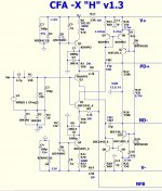
I redrawing Symetri under Diptrace. I don't know if it is a mistake but i found a difference between schematic and layout => C9 (R33 if we follow straight the schematic) should be connected to Q8 collector and C33 but not to Q8 base
for some of the newer CAD users that may drop into this thread, this is an example of a benefit of using a tool with well-integrated schematic capture and layout.
us old geezers need this kind of help anyways!
🙂
mlloyd1
Then you need to get the schematic right. I still get reversed diodes and caps.😀
I haven't messed about with the simulation, can anyone say definitively that the capacitance multipliers MUST be connected to G2 rather than the G1 star? Just continuing with my alternate layout and will find it really hard to use the G2 point for the multipliers. Thought / opinions welcomed.
way too much gain , not enough phase margin.
I'm finalizing the design with 68R's (Q1-4) 47R's(Q7-10) , the fixed (collector)
to NFB network PCB error , and 22-33pF's for miller.
What you do with the 22's is have the amp with gain at or above the point
that the phase is 180 degrees + = oscillator.
Some transistors might work with 22 , better to increase the range of
beta with more degeneration to accommodate "whatever" a builder
might have in the parts drawer.
Thank you for pushing the limits , I'd rather have a very stable IPS.
(and NO complaints).
OS
Hi Pete,
I've had it playing all morning. Plays great. I wanted to note this in case ut matters. When I have R23/R30 set to 11mA, R15/R16 are at 4.2mA. Would dropping emitters for Q7-10 to 47R help/hurt?
G2 could also go to your main PS star.
This is about the only forum project that gives this much flexibilty
for earthing.
The reason for this , If you wish for "overkill" ,you can isolate the IPS's
ground from any OPS current pulses. NO other amp project allows this.
You are stuck with wherever they chose to tap the main star.
You start to talk like Carlos, but he is doing that with much more style.
You start to talk like Carlos, but he is doing that with much more style.
He's still got Carlos beat with the Honeybadger video.😀
Is it really a competition going on? I think there are two different approaches and one of them is based on making this a commercial endeavor. I have examples from both and they are very different styles completely. One all thru hole and one based on smd. I haven't kept up with the First One and now it seems there are two versions of that with one with one pair of outputs and a second now with a pair.
"Can't we all get along".
"Can't we all get along".
Is it really a competition going on? I think there are two different approaches and one of them is based on making this a commercial endeavor. I have examples from both and they are very different styles completely. One all thru hole and one based on smd. I haven't kept up with the First One and now it seems there are two versions of that with one with one pair of outputs and a second now with a pair.
"Can't we all get along".
I think you confuse Carlos (destroyer X) and Andrej (Lazy Cat). Carlos has his 'DX Corporation', and imaginary company, and Andrej has moved solidly into closed design commercial endeavours.
Hi Pete,
I've had it playing all morning. Plays great. I wanted to note this in case ut matters. When I have R23/R30 set to 11mA, R15/R16 are at 4.2mA. Would dropping emitters for Q7-10 to 47R help/hurt?
That's a little higher than the 1.8ma specified , but 2.1 is not bad ... quite
within the q1-4 optimum. I think dropping the Q7-10 resistors would give
1.8ma= 11ma ratio and increase the total gain a tad. "If it ain't broke , why fix it?" 😀
Dadod , I'm about to get my SHOTGUN (like Carlos) ... that's his "style" !
Edit - there ... Carlos style.
OS
Attachments

Last edited:
Is it really a competition going on? I think there are two different approaches and one of them is based on making this a commercial endeavor. I have examples from both and they are very different styles completely. One all thru hole and one based on smd. I haven't kept up with the First One and now it seems there are two versions of that with one with one pair of outputs and a second now with a pair.
"Can't we all get along".
I ain't sellin' stuff ? LC is , says other stuffs are poop. Douglas self
even just said we all need to be building "blameless's" (signal tranfer PCB's).
So , there does seem to be some dislike going 'round , as every Badger
or Slewmaster is one less board sold in a finite market.
Oh , well .
OS
Pete,
I wasn't saying you are selling anything, I was referring to LC, he is in this for commercial gain. I've seen the posts by D. Self, now he is even trying to tell B. Cordell he doesn't like the way he presents his work in his book. I do find him a bit condescending that is for sure. I haven't looked anywhere else at amplifier design but your threads for a long time now, I love what you are doing.
I wasn't saying you are selling anything, I was referring to LC, he is in this for commercial gain. I've seen the posts by D. Self, now he is even trying to tell B. Cordell he doesn't like the way he presents his work in his book. I do find him a bit condescending that is for sure. I haven't looked anywhere else at amplifier design but your threads for a long time now, I love what you are doing.
Pete,
I wasn't saying you are selling anything, I was referring to LC, he is in this for commercial gain. I've seen the posts by D. Self, now he is even trying to tell B. Cordell he doesn't like the way he presents his work in his book. I do find him a bit condescending that is for sure. I haven't looked anywhere else at amplifier design but your threads for a long time now, I love what you are doing.
Cordell admits the validity of CFA and symmetrical designs in the audio world.
Self is "My way or the highway". Very narrow design scope , great book
if you just want to build a "blameless"
Now he is condemning Cordell for not having an AP , or relying on any simulated
data.
Self's book even discounts the EF3 as unstable , Bob actually personally
helped me make the slewmaster EF3 possible. 😎
OS
- Home
- Amplifiers
- Solid State
- Slewmaster - CFA vs. VFA "Rumble"