Hi OS,
I redrawing Symetri under Diptrace. I don't know if it is a mistake but i found a difference between schematic and layout => C9 (R33 if we follow straigh the schematic) should be connected to Q8 collector and C33 but not to Q8 base
I did a sim of the errata and there was a peak in the response, exactly as Terry demonstrated in real life. The 22 ohm resistors as originally specified are likely fine with C9 connected as shown in the schematic.
After looking there is no reason to swap R33 and C9. They are in series. Main thing is they need to attach to the collector of Q8 and not the base. I can accomplish this with just one trace cut and a jumper.
I'm going to try it and get back to you.
Blessings, Terry
I'm going to try it and get back to you.
Blessings, Terry
OMG , I did screw up. No wonder it oscillated with 3.9pF !
I bet it would run nice with those 22's , UGLF must of been at 5mhz.
OS
I bet it would run nice with those 22's , UGLF must of been at 5mhz.
OS
I'll test it in the morning. First with the jumper then I'll try putting the 22r resistors back in.
OK I cut the track and installed the jumper. Plays nice and seems more stable. Then I swapped back the 22R resistors. Unfortunately, I mixed up which side I changed and failed too monitor the side with the changes. By the time I noticed it I had blown a fuse, an output and cap multiplier. After spending close to an hour repairing the OPS, I started testing again using my light bulb tester. Bias was sky high again. I tested the IPS stand alone using resistors again between ND, PD and NFB. I am seeing almost the exact thing I saw before. My opinion? This IPS will not work with 22R in the emitter resistor positions. Maybe you have some more ideas.
OK I cut the track and installed the jumper. Plays nice and seems more stable. Then I swapped back the 22R resistors. Unfortunately, I mixed up which side I changed and failed too monitor the side with the changes. By the time I noticed it I had blown a fuse, an output and cap multiplier. After spending close to an hour repairing the OPS, I started testing again using my light bulb tester. Bias was sky high again. I tested the IPS stand alone using resistors again between ND, PD and NFB. I am seeing almost the exact thing I saw before. My opinion? This IPS will not work with 22R in the emitter resistor positions. Maybe you have some more ideas.
way too much gain , not enough phase margin.
I'm finalizing the design with 68R's (Q1-4) 47R's(Q7-10) , the fixed (collector)
to NFB network PCB error , and 22-33pF's for miller.
What you do with the 22's is have the amp with gain at or above the point
that the phase is 180 degrees + = oscillator.
Some transistors might work with 22 , better to increase the range of
beta with more degeneration to accommodate "whatever" a builder
might have in the parts drawer.
Thank you for pushing the limits , I'd rather have a very stable IPS.
(and NO complaints).
OS
Hey Pete,
That did the trick. I have R23/R30 set to 9mA which give me the same bias on the OPS that I had with other IPS. I haven't checked the IPS output current. Square waves look as good as anything I have tested. I'm going to change out the 22R resistors on the other channel and then give it a listen.
Blessings, Terry
amazing footprints of the symetri in real world! i love the way OS play his simulation rig. 🙂
amazing footprints of the symetri in real world! i love the way OS play his simulation rig. 🙂
Thank you Jaag . 🙂 You make it sound like a guitar. 😀
There is a harder side to things , and I give Terry , Jeff , and Thimios
a BIG BOW !!! .... Building is so hard for me.
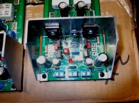
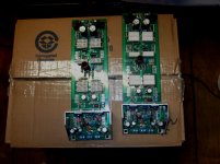
Just finished both of the new slewmaster V3's. (below 1-2)
Looped one back - it works ! Had to remill JW's driver heatsinks - drivers
are closer together , driver Vbe is nearer to middle. 🙁
Edit - the old V2's I had are free to any that would pay for the shipping -
they are in a padded flat rate ready to go. No pads or traces were damaged
by harvesting. Inductors, fast-ons, to-126's , all 1/4w resistors are untouched.
Now I just load all the outputs - I know they will work after the loopback.
real nice looking PCB , especially the multiplier/driver end. Nice little led
to show it's on (mosfet would have one in a different place).
Man , symetri would "scream" on this output stage.
OS
Attachments
Last edited:
way too much gain , not enough phase margin.
I'm finalizing the design with 68R's (Q1-4) 47R's(Q7-10) , the fixed (collector)
to NFB network PCB error , and 22-33pF's for miller.
What you do with the 22's is have the amp with gain at or above the point
that the phase is 180 degrees + = oscillator.
Some transistors might work with 22 , better to increase the range of
beta with more degeneration to accommodate "whatever" a builder
might have in the parts drawer.
Thank you for pushing the limits , I'd rather have a very stable IPS.
(and NO complaints).
OS
I had wondered how it would work if we only change out the 22Rs for Q1-4 but I have switched them three times and I don't want traces to start lifting so I think I'll stop while I'm ahead. I may try the 47R for Q7-10 if I feel spunky tomorrow. 😀 It is very stable as I have it now. I pushed it hard with 70V rails for a couple of hours and it just sang.
Blessings, Terry
Pete,
email sent re old output boards
No PM or email. (yet - slow ??)
As long as it don't cost me ... paypal , USPS - gone !
OS
Os, what supply would you recommend for the new version slewmaster with 5 pair IRFP240 fets.
1. 450VA at +- 70V or
2. 800VA at +- 52V.
It will be powering both channels.
The load will primarily be 4 Ohm speakers. Where can I find the latest BOM for the slewmaster.
1. 450VA at +- 70V or
2. 800VA at +- 52V.
It will be powering both channels.
The load will primarily be 4 Ohm speakers. Where can I find the latest BOM for the slewmaster.
Os, what supply would you recommend for the new version slewmaster with 5 pair IRFP240 fets.
1. 450VA at +- 70V or
2. 800VA at +- 52V.
It will be powering both channels.
The load will primarily be 4 Ohm speakers. Where can I find the latest BOM for the slewmaster.
Unfortunately , the BOM is the schematic. Stupid LT won't let you export the netlist to text. Below is that netlist , I you want.
For 4R , your SOA would be greatest with the +- 52V. In fact ,about a 15A
fuse range - wow ! You most likely could short it out , just burn a fuse.
I've done that with just my 3 pair MT-200 setup , replaced fuse - runs
nice.
800VA plus 60-100Kuf should be enough. My 1Kva/80K barely ripples at
all.
OS
Attachments
Os, thanks but I cannot open the net files. Is there a way to convert them to pdf ?, also which is the latest slewmaster schematic ?
Thanks
Jan
Thanks
Jan
Os, thanks but I cannot open the net files. Is there a way to convert them to pdf ?, also which is the latest slewmaster schematic ?
Thanks
Jan
It opens with Notepad
JWL,thanks, got it. What wattage value will the small resistors be ? .25 or .5 watt. I will be using +-52Vdc rails so all caps can be 63V ? What is the difference of the schematic if using fets i.s.o bipolars ?
Regards
Jan
Regards
Jan
JWL,thanks, got it. What wattage value will the small resistors be ? .25 or .5 watt. I will be using +-52Vdc rails so all caps can be 63V ? What is the difference of the schematic if using fets i.s.o bipolars ?
Regards
Jan
1/4 or even 1/8w. The schema shows it ... bridge the smd jumpers ,
use the "B" capacitor s , use the "B" driver row. Oh , red LED for D102
and 1K for R113.
Bridge D102 and use all "A" for BJT.
Gotta write a book for this !
OS
Os, sorry for stupid questions but I'm not sure about where G1 and G2 is ?🙂 It is not the same ground ?
And Q105/106 get's left out of the circuit as well. R114/115 changes to 10 ohm with 50V rails ?
And Q105/106 get's left out of the circuit as well. R114/115 changes to 10 ohm with 50V rails ?
Last edited:
Os, sorry for stupid questions but I'm not sure about where G1 and G2 is ?🙂 It is not the same ground ?
And Q105/106 get's left out of the circuit as well. Is that correct ?
The schema should show this , I'm going to have to write a book.
Yes , just checked it ... All the "B" options are on both the schema and
marked on the PCB.
Marked in red on the schema also says "all G2's" (connected to G1).
I'm using a 275mm black wire with 2 fastons to connect G1-G2.
G2 could also go to your main PS star.
This is about the only forum project that gives this much flexibilty
for earthing.
The reason for this , If you wish for "overkill" ,you can isolate the IPS's
ground from any OPS current pulses. NO other amp project allows this.
You are stuck with wherever they chose to tap the main star.
I've ran both ways , both are silent (no hum).
A book with pictures would still be helpful , I'm only now collecting
photo's of the standard BJT build. I only ran the board
once.
OS
- Home
- Amplifiers
- Solid State
- Slewmaster - CFA vs. VFA "Rumble"