Oh , I forgot to mention ....
Symetri and "AE" are NOT (typical) cascoded VAS's. If the possibility exists to hear a
difference in SQ , these two IPS's are NOT cascoded like most others. 😕
OS
Symetri and "AE" are NOT (typical) cascoded VAS's. If the possibility exists to hear a
difference in SQ , these two IPS's are NOT cascoded like most others. 😕
OS
I can help-you (if you want) to make-it on your web site (I was too a web designer at the end of my professional life ;-).
We will talk .... my concern is for the builder - really. I see scope of "confusion".
OS
Not sure it is a bad thing, I believe cascodes has a special signature. Well, this idea of a VAS working in base common configuration is very interesting, and absolutely in the CFA spirit ( it is that way feedback is working in a CFA IPS). Something to dig ? It is the best configuration for speed (HF), and, in CFAs, we are searching for speed, don't we ?Symetri and "AE" are NOT (typical) cascoded VAS's. If the possibility exists to hear a difference in SQ , these two IPS's are NOT cascoded like most others.
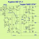
Here's the PDFs for my Kypton-ND layout.
Just two things - bottom layer ground return .... all traces individually enter the star.
More serious , the full signal NFB traces . Keep as much clearance as possible
from other tracks until it enters the first pair of resistors.
After that , at the CFB node ... it is 1/27th full level.
One of these IPS's could nearly create household AC levels ! (creepage considerations).
ND is full rail or a 12v option to Q1/2 collectors. Not a
jumper across the zener dropping resistors. Q1 and 2 collector can connect
to either "side" of R14 or 15. There could be confusion here.
all else looks good , double check the screens (backward stuff 😛😀).
OS
What ground traces should I merge before the enter they star?
I can swap some resistors to shorten the NFB traces
Those jumpers under R14 and R15 are voltage selector for Q1 and Q2. Three pin jumpers, bridge one pair or the other.
Last edited:
1 -What ground traces should I merge before the enter the star?
2 -I can swap some resistors to shorten the NFB traces
3 -Those jumpers under R14 and R15 are voltage selector for Q1 and Q2. Three pin jumpers, bridge one pair or the other.
#1 - shown (below)
#2 - just try to get as many mm (clearance) between any full current/full AC voltage NFB trace and any other. The drawn suggestion is just that ....
This is more critical on a CFA , many ma current at high signal levels.
#3 is good.
Edit - shortest path .. I see that "substar" for the input/servo - route that to the main star without going all the way
around the edge of the PCB.
OS
Attachments
Last edited:
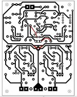
Jeff , you see the prototype below. Main G2 star with the servo/input star connecting
with one trace.
R12/13 ground returns for the current feedback are quite short. Current pulses
from the feedback and the 12V decoupling fully cancel at the G2 pad.
This makes a good place for the ground of C2/C5/R2 to connect.
Any similar scheme will be OK.
OS
with one trace.
R12/13 ground returns for the current feedback are quite short. Current pulses
from the feedback and the 12V decoupling fully cancel at the G2 pad.
This makes a good place for the ground of C2/C5/R2 to connect.
Any similar scheme will be OK.
OS
Attachments
Pete,
this thread has been a builders wonder. As seen of Terry you have kept people very busy with all these designs, and a couple of unstable input sections says a lot for the quality of the designs. I am sure you could solve those instabilities if you wanted to spend the time.
I started my own thread on integration of the power amp and digital side for a powered loudspeaker and have already found another who has helped to refine what I am trying to do, a kindred spirit trying to bring the latest developments to the public. I have taken his concept of internal and external building blocks and made that my goal. So I have simplified what I now will put inside the enclosure. Just a pair of your amp designs with input sections, a dsp for xo, FR, and perhaps later room correction, two dacs, one A/D and one D/A. I still have much to learn how to do just that but that is the plan.
All the other functions such as USB, Bluetooth and now WiSA wireless and anything else will be external to the speakers. I have had an idea for a long time for a modular system where you can add new features without having to change what you already have, just add another module to the system. I want that to look as great as my speakers, it will not be in a rectangular enclosure.
I''ll keep my eyes on your preamp thread for more ideas. Anyone is welcome to that other thread, I started it but know I am not the only one interested in self powered speakers.
An Active loudspeaker UNIFICATION thread
Last edited:
Jeff -
Looking better , do look at the prototype - it's layout is among my best.
It might be a bit better. The autorouting of your CAD is not the same as
"human based autorouting" (multiple considerations).
The brain can accommodate I / V / AC , loop area and beauty simultaneously. 😀
OS
Looking better , do look at the prototype - it's layout is among my best.
It might be a bit better. The autorouting of your CAD is not the same as
"human based autorouting" (multiple considerations).
The brain can accommodate I / V / AC , loop area and beauty simultaneously. 😀
OS
I had the input and servo on one ground trace, and servo decoupling cap grounds on another trace. They were the two ground traces that merged just above the star ground so it could all enter at the center between C3 and C4.
I'd like to swap R12 & 16, R13 & R17 to shorten the traces but there's no room to squeeze a ground through. This is a reworked Kypton-C board. I'm really remembering why I switched to Diptrace. I think I should make some time to create Slew style components for Diptrace after the Pitchfork boards are completed. The default components aren't very nice to rework and the artwork isn't as good but it's much easier to look at for long periods of time while designing.
I'd like to swap R12 & 16, R13 & R17 to shorten the traces but there's no room to squeeze a ground through. This is a reworked Kypton-C board. I'm really remembering why I switched to Diptrace. I think I should make some time to create Slew style components for Diptrace after the Pitchfork boards are completed. The default components aren't very nice to rework and the artwork isn't as good but it's much easier to look at for long periods of time while designing.
Jeff -
Looking better , do look at the prototype - it's layout is among my best.
It might be a bit better. The autorouting of your CAD is not the same as
"human based autorouting" (multiple considerations).
The brain can accommodate I / V / AC , loop area and beauty simultaneously. 😀
OS
This is still drawn in Sprint. The scroll wheel zoom making the cursor jump off the screen is driving me nuts! This is how I navigate a design in any other software I use so it's second nature for me to use it.
OS,
I apologize that I didn't put the diptrace on disk yet. I will do it today and get that out to you.
I apologize that I didn't put the diptrace on disk yet. I will do it today and get that out to you.
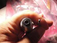
Hello guys sorry that this question is not about slewmaster subject is about a tool, what size tool tapping wrench do I need for 4-40 tap ?
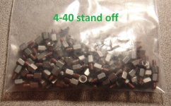
I purchase a bunch of 4-40 stand off stainless steel and I want to begin doing tapping stuff for some projects that I have "in boxes" 😛
Regards
Juan
I purchase a bunch of 4-40 stand off stainless steel and I want to begin doing tapping stuff for some projects that I have "in boxes" 😛
Regards
Juan
Attachments
Hello guys sorry that this question is not about slewmaster subject is about a tool, what size tool tapping wrench do I need for 4-40 tap ?
I purchase a bunch of 4-40 stand off stainless steel and I want to begin doing tapping stuff for some projects that I have "in boxes" 😛
Regards
Juan
4-40 for aluminium you need a drill N° 43 (0.0890"), for steel use N° 41 (0.0960").
You can use your google search any time just ask for "tap drills"
Antonio
Will this help Juan?
Tap Drill Chart
oh yeah that does help a lot too, but I just need to know what size tool I need to hold the 4-40 tap I have the wrong size tool 🙂 is ok I love tools but I need the correct one I don't want it to try out and then break the tap, I read those things are like glass fragile
Regards
Juan
Attachments
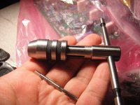
Hi Juan.
That one is too big. Try this one.
New Adjustable Tap Handle Reamer Wrench M1 to M8 1 16 1 4 | eBay
That one is too big. Try this one.
New Adjustable Tap Handle Reamer Wrench M1 to M8 1 16 1 4 | eBay
- Home
- Amplifiers
- Solid State
- Slewmaster - CFA vs. VFA "Rumble"