Why so hard on the VFA ? The do REAL well on LF duty.
A VFA for your 20-100hz sub , and a pair of CFA's for the "soundstage".
OS
Cause I have a full range speaker system to use it on.... no separate sub is used/needed. But needs a lot of power/dynamics/head-room for the 2 - 15 inch bass speakers per channel.
On another system, I'll need a sub ( 2-18 inch drivers) and agree that a vfa will be good there.
THx-RNMarsh
Last edited:
Yeah I remember that from his book and I've considered it a few times. The trick is coming up with a system that will allow an I2C/SPI controlled pot to vary the bias without anything blowing up. I don't know if this will work, but I figured I'd give it a try and see.
Thanks OS, that seems fairly simple RE setting the CFA up for lower rails. With regards to the cap multiplier, I figure with it in place that it willdecrease the output swing capability of the amp by limiting the range the VAS can swing?
On the lower voltage CFA amp this isn't so much of a problem and I was perhaps thinking of regulating the rails for the small signal circuitry anyway.
found what may be a better link after the edit period expired:
http://www.embedded.com/print/4015856
mlloyd1
http://www.embedded.com/print/4015856
mlloyd1
CFA X 1.3
I don't recommend compensation between collectors and ground.
This method kill all the high frequencies.
Use the alternative methode ,CM1 CM2 .
PS CFA X 1.3 Gain=26
CFA-X Gain=30
Thimios.
I don't recommend compensation between collectors and ground.
This method kill all the high frequencies.
Use the alternative methode ,CM1 CM2 .
PS CFA X 1.3 Gain=26
CFA-X Gain=30
Thimios.
Attachments
Last edited:
I don't recommend compensation between collectors and ground.
This method kill all the high frequencies.
Use the alternative methode ,CM1 CM2 .
PS CFA X 1.3 Gain=26
CFA-X Gain=30
Thimios.
 😎
😎...and listening test?
Like a CFA my friend!🙂
...and listening test?
The Joy of tweeters!
Crystal clear high frequencies.
Last edited:
Jason, can you *please* finish your CFA-X layout and get it to the board house so we can join the fun? 🙂
It's useful if we have others builders and other opinions of course🙂Jason, can you *please* finish your CFA-X layout and get it to the board house so we can join the fun? 🙂
Like a CFA my friend!🙂
The Joy of tweeters!
Crystal clear high frequencies.
How about "spooky-leach" IPS? Sound like a CFA too?
Leach is a VFA.
I'm mostly interested in the Wolverine but I think there would be more interest in the CFA designs.
I'm mostly interested in the Wolverine but I think there would be more interest in the CFA designs.
do you want a spooky, leach vs cfa test?
Give me some time.....i can't afford all this.
Give me some time.....i can't afford all this.
Last edited:
Jason, can you *please* finish your CFA-X layout and get it to the board house so we can join the fun? 🙂
I am working on it. I am still under some personal obligations at the moment making it difficult to spent the extra time, so though there is progress it is slower than I'd like. I will let folks know when I'm ready for a pre-order review.
All good I know how it feels having too much to do.
Please add me to the preorder list for 2 boards.
Please add me to the preorder list for 2 boards.
Sorry my friend i haven't built this .....mayby later.Leach is a VFA.
I'm mostly interested in the Wolverine but I think there would be more interest in the CFA designs.
do you want a spooky, leach vs cfa test?
Give me some time.....i can't afford all this.
😀 I just want to know if VFA have high slew rate like CFA, is the sound same?
😀 I just want to know if VFA have high slew rate like CFA, is the sound same?
Back EMF at LF (and Z curves) affect CFA's differently than a VFA.
I'm simulating loudspeaker Z curves on these amps now...
Perhaps this is why Thimios favored them (VFA's) in his "bass" assessment.
As we are using the same OPS ... it has to be the FB . 😕
As far as CFA's ... the current/voltage inputs are split on the "gnome" ,
the same 2 devices do BOTH on the CFA-X's . This also has effect.
OS
I don't recommend compensation between collectors and ground.
This method kill all the high frequencies.
Use the alternative methode ,CM1 CM2 .
PS CFA X 1.3 Gain=26
CFA-X Gain=30
Thimios.
This CFA-XH is indeed nice ... Good job , I did notice "CM1/2" gives
better performance in LTspice.
Thank you ... I now had a "sure bet" for my build.
OS
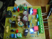
I got the JTK-CFA IPS working today. I tried the values in the schematic from post #2110. The lowest I could get the output was 8.1 mA. Something else needs to be changed as well to get to 4.5mA. I just changed back to the values Jason gave me and all is well. The 100R in R113 works. The heatsink is about as hot as I would expect. Probably want to go to 150R if you are using a thin sheet of aluminum.
I played it for a couple hours today. It sounds really good, especially considering it is an IPS that was designed to feed a couple MOSFETs.
Blessings, Terry
I played it for a couple hours today. It sounds really good, especially considering it is an IPS that was designed to feed a couple MOSFETs.
Blessings, Terry
Present summary/"shootout"
I've changed and refined most of the original
amp designs (since the start of the thread).
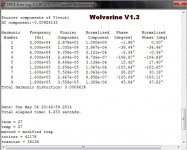
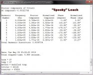
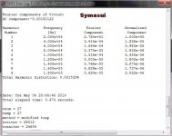
The top 5 are ... (THD wise - below 1-5)
1-Wolverine
2-Spooky leach
3-Symasui
4-CFA-XH
5-Gnome
The fastest are...(slew)
1-CFA-XH
2-Gnome
3-Spooky ... the only VFA to even come close to CFA 😀 .
The cheapest .... $$$ 😀
CFA-XH - @ 10-12$
The other 4 are <20$ IPS's.
These are the 5 final SOTA IPS's , the designs are about
as good as their topologies allow.
Of course , we could make a 40 device "instrumentation amp " ...
but would it be built. 😕
OS
I've changed and refined most of the original
amp designs (since the start of the thread).
The top 5 are ... (THD wise - below 1-5)
1-Wolverine
2-Spooky leach
3-Symasui
4-CFA-XH
5-Gnome
The fastest are...(slew)
1-CFA-XH
2-Gnome
3-Spooky ... the only VFA to even come close to CFA 😀 .
The cheapest .... $$$ 😀
CFA-XH - @ 10-12$
The other 4 are <20$ IPS's.
These are the 5 final SOTA IPS's , the designs are about
as good as their topologies allow.
Of course , we could make a 40 device "instrumentation amp " ...
but would it be built. 😕
OS
Attachments
Last edited:
I got the JTK-CFA IPS working today. I tried the values in the schematic from post #2110. The lowest I could get the output was 8.1 mA. Something else needs to be changed as well to get to 4.5mA. I just changed back to the values Jason gave me and all is well. The 100R in R113 works. The heatsink is about as hot as I would expect. Probably want to go to 150R if you are using a thin sheet of aluminum.
I played it for a couple hours today. It sounds really good, especially considering it is an IPS that was designed to feed a couple MOSFETs.
Blessings, Terry
The final VAS current on jason's board has 3 variables.
1- the VAS Re's
2- The resistors from base to rail on these devices, (R5/6) in the post.
3- the IP current. Jason's 500R VR1/3 need to go a little higher to get
<1.7ma at the IP pair. 1K trimmers would give you a range of .5ma -
(infinity - too much).
PS- I use a fixed resistor in series with the trimmer for safety and a limited
range of 3- 7ma VAS ! (470 -670R at CCS)
You should be able to get ANY VAS current with these changes.
OS
Last edited:
- Home
- Amplifiers
- Solid State
- Slewmaster - CFA vs. VFA "Rumble"