I do think PSSR is important, mostly to keep PSU ripple out of the output signal, but to say it steel locks the base response goes against my experience. Try to draw a equivalent circuit with the PSU-caps, the amplifier the PSU midpoint and your speakers as elements, then you see that PSSR only matters if GND is solid. And with weak supplies it is NOT.
I tried this first time only with C13-14(33p) installed but i see on scope that oscillate,did you mean that i must increase these values without adding CM1 CM2?I intended for the use of EITHER "cm1/2" OR C13-14 in addition to R17/18.
... It will work , but either the "shunt" OR miller is used (not both).
You are likely overcompensated !
OS
Last edited:
I tried this first time only with C13-14(33p) installed but i see on scope that oscillate,did you mean that i must increase these values without adding CM1 CM2?
Try just CM1/2 =33p .
or,You could also increase c13-14 .. try 47P ?
PS - glad I included CM1/2 - "cover my ar$e" .... 😀
I have also seen some OEM's use a combination ... 33-47p C13-14
and a very low value - 5-10p for Cm1/2.
So , your combo is an accepted practice.
OS
Ok i will try all these tomorrow and report again.Try just CM1/2 =33p .
or,You could also increase c13-14 .. try 47P ?
PS - glad I included CM1/2 - "cover my ar$e" .... 😀
I have also seen some OEM's use a combination ... 33-47p C13-14
and a very low value - 5-10p for Cm1/2.
So , your combo is an accepted practice.
OS
PS keep in mind that these trimmers cm1,2 (2-22pf) isn't possible to fine square wave at its lower value.
Thanks.
Last edited:
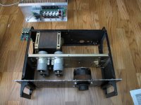
Finally decided to make a REAL test supply for the SlewMonster
No more messing about with little test supplies, testing a BIG amp needs a BIG supply! This is going to be made from an old HH V800 chassis and components.
Planning on switchable output, +/-40V or +/-80V. Softstart, switchable current limiting (simple on/off), integrated variac, and voltage and current meters.
The SlewMonster is the inspiration to go big, I feel I should have a bigger supply on hand to ensure all will be well with future builds.
Attachments
Anyone consider a switch mode power supply to run these combinations? I am only thinking about this because of space constraints, but wonder how the combination would work together?
CFA vs. VFA "Rumble" Capacitive Loads.
Are there any technical reasons why CFA or VFA would have greater stability or superior sound when driving a large capacitive load like an electrostatic speaker or large Capacitor value in a filter?
On the bench, an 8-ohm resistor load in parallel with a capacitive load of a few microfarads generates a noticeably(O'scope obvious) larger power supply noise with a CFA front end than it does with my VFA front end. The higher slew rate of the CFA could be part of the difference. The VFA front end includes TMC filtered feedback, and this could be part of the difference. On the bench, a high gain VFA front end( symmetric differentials + cascodes + current mirrors) measures much lower THD than a CFA-X "H" v1.3. I am still learning how to optimize CFA.
With easy load efficient speakers playing familar music, I cannot hear any obvious difference between my all-bipolar VFA and the CFA-X "H" v1.3.
No more messing about with little test supplies, testing a BIG amp needs a BIG supply! This is going to be made from an old HH V800 chassis and components.
Planning on switchable output, +/-40V or +/-80V. Softstart, switchable current limiting (simple on/off), integrated variac, and voltage and current meters.
The SlewMonster is the inspiration to go big, I feel I should have a bigger supply on hand to ensure all will be well with future builds.
That could be quite a doorstop ! 😀
800VA Iron cube ?
OS
May well be bigger than that. This was professional level PA rated at 400W x2 into 4Ω continuous.
No more messing about with little test supplies, testing a BIG amp needs a BIG supply!
The SlewMonster is the inspiration to go big, I feel I should have a bigger supply on hand to ensure all will be well with future builds.
😎🙂 Thats what I want -- high power, fastest SR, Lowest thd etc. Best of everything CFA has to offer. Plus, everything VFA has to offer as well without being a VFA.
THx-RNMarsh
😎🙂 Thats what I want -- high power, fastest SR, Lowest thd etc. Best of everything CFA has to offer. Plus, everything VFA has to offer as well without being a VFA.
THx-RNMarsh
Why so hard on the VFA ? The do REAL well on LF duty.
A VFA for your 20-100hz sub , and a pair of CFA's for the "soundstage".
There is no need for slew at 45hz !!
PS - I am continuing work on the "Hybrid" (oneshot).
Also , a SMPS + CFA .... might approach the wolverine PSRR.
OS
Hi guys
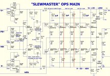
I'm about to start my "MONSTER" and wanted to confirm that the schematic in post #504 is still current.
I'm going to run these from 70V rails... is the driver emitter resistor (68R) a little low perhaps? Would 100R or even 150R be more suitable for this voltage?
Also what's the word on Csa/Csb? This OPS will be MJE340/NJW3281/MJL21194 and compliments.... thinking I might install some 68p np0's between the driver base/collectors to tame any oscillation.
Attachments
Hi Christian,
I would go with at least 100R for R113. That is what I just installed. They still run a little warm but I can keep my hand on the heatsink now. Hopefully I can give a full report later today. I had some bad caps for R125\127 and am trying to reform some. If that goes well it will be singing today. I installed CSA/CSB. I'm not sure if they were needed but they don't seem to hurt. Don't forget to install that long jumper tying the two G2's together.
I would go with at least 100R for R113. That is what I just installed. They still run a little warm but I can keep my hand on the heatsink now. Hopefully I can give a full report later today. I had some bad caps for R125\127 and am trying to reform some. If that goes well it will be singing today. I installed CSA/CSB. I'm not sure if they were needed but they don't seem to hurt. Don't forget to install that long jumper tying the two G2's together.
Is there any kind of limitation to the design regarding how low you can take the voltage rails? I am currently in the process of laying out a 2 pair wolverine for the bottom of a three way, intended to be run from 40 volt rails. They will be bridged if need be (I would like more power but I'm re-using an old transformer), but I also intend on doing a class A something or other, run from around ~24 volt rails for the mids and tweets.
I am going to attempt a micro controller controlled variable bias output stage, that keeps the thing running in class A, up to a point, by sensing the current through the RE resistors and am interested in trying the CFA input stage too. Would this design translate well to 24 volt rails? I know traditionally that current source controlled amps work fine on lower rails, but the CFA input is completely new to me.
I am going to attempt a micro controller controlled variable bias output stage, that keeps the thing running in class A, up to a point, by sensing the current through the RE resistors and am interested in trying the CFA input stage too. Would this design translate well to 24 volt rails? I know traditionally that current source controlled amps work fine on lower rails, but the CFA input is completely new to me.
Is there any kind of limitation to the design regarding how low you can take the voltage rails? I am currently in the process of laying out a 2 pair wolverine for the bottom of a three way, intended to be run from 40 volt rails. They will be bridged if need be (I would like more power but I'm re-using an old transformer), but I also intend on doing a class A something or other, run from around ~24 volt rails for the mids and tweets.
I am going to attempt a micro controller controlled variable bias output stage, that keeps the thing running in class A, up to a point, by sensing the current through the RE resistors and am interested in trying the CFA input stage too. Would this design translate well to 24 volt rails? I know traditionally that current source controlled amps work fine on lower rails, but the CFA input is completely new to me.
Here is the "lowdown" , on this.
The wolverine (and all the VFA's) have stellar PSRR ... you can , omit
the capacitance multipliers here. Just jumper C-E on the multiplier
semi's (eliminate it's associated diode,R's , and main cap).
Leave the final output decoupling nearest to PD+/ND-. You will gain 2+V
on the rails.
Running the wolverine on <30v , you also might want to halve any rail dependent network.
R9,16,19 and 20 @ 1/2 value will ensure spec. operation.
PS - all these VFA ips's can run down to OP-amp voltages (+/- 15V).
The CFA's with regulated +/- 12v supplies would do with >20V and
you would have to adjust the Zener dropping resistors.
OS
Hi guys
I'm about to start my "MONSTER" and wanted to confirm that the schematic in post #504 is still current.
I'm going to run these from 70V rails... is the driver emitter resistor (68R) a little low perhaps? Would 100R or even 150R be more suitable for this voltage?
Also what's the word on Csa/Csb? This OPS will be MJE340/NJW3281/MJL21194 and compliments.... thinking I might install some 68p np0's between the driver base/collectors to tame any oscillation.
Still4forgiven has spoken. 68-82R = a real large compound (finned) HS ...
(like the ones in a computer PS).
100-150R = flat plate of aluminum
220R (like the HK680) = just a piece of roof flashing.
One thing to consider with changing driver Re - you might either have to adjust IPS VAS current or change the series resistor next to
the main OPS bias(R106) to retain a centered optimal OP bias range (R107 , either (330/390 instead of 470R).
OS
Hi Christian,
I would go with at least 100R for R113. That is what I just installed. They still run a little warm but I can keep my hand on the heatsink now. Hopefully I can give a full report later today. I had some bad caps for R125\127 and am trying to reform some. If that goes well it will be singing today. I installed CSA/CSB. I'm not sure if they were needed but they don't seem to hurt. Don't forget to install that long jumper tying the two G2's together.
Thanks Terry, I'll start with 150R and go from there. If you still have some of the 820u filter caps that Kevin specified on the LTT4 then these are ideal for C125/127. They're the perfect lead pitch and case size; the extra capacitance can only help when the outputs are drawing heavy currents.
just to throw something else at you, if you want to lock in a class A bias value, what about the scheme that Doug Self used in a class A circuit? I saw it in one of his books and /or the amplifier distortion articles series. I think it was a couple of small signal transistors and a low voltage reference (1.5v or so?) and some resistors. I think it was a diff amp measuring voltage across the output stage emitter resistors and comparing that to a scaled version of the reference. I remember reading about it because of a comment he made that it locked the bias value very tightly, unlike some other circuits where the bias wandered around like a drunken sailor. Having seen drunken sailors, the imagery stuck with me.
🙂
Anybody remember the circuit I'm talking about? It was pretty simple but i don't recall the schematic exactly. Doug is on here somewhere too.
mlloyd1
edit:
ok, i found a link to the schematic here:
Self on Audio - Doug Self, Douglas Self - Google Books
🙂
Anybody remember the circuit I'm talking about? It was pretty simple but i don't recall the schematic exactly. Doug is on here somewhere too.
mlloyd1
edit:
ok, i found a link to the schematic here:
Self on Audio - Doug Self, Douglas Self - Google Books
... but I also intend on doing a class A something or other, run from around ~24 volt rails for the mids and tweets.
I am going to attempt a micro controller controlled variable bias output stage, that keeps the thing running in class A, up to a point, by sensing the current through the RE resistors ...
Last edited:
- Home
- Amplifiers
- Solid State
- Slewmaster - CFA vs. VFA "Rumble"