It is worth it, always KISS-es, just not too many. 😎
I got it ... (below 1). Had to redesign the whole hawksford 🙁 .
To save space , can I discuss the blocker caps ? I use 1Kuf NP.
1. -can I use small polarized 10-16V caps ?
2.and - to make for "mil grade bombproof" , a reverse diode on these caps?
If something happened , to avoid "EXPLODING" 😱 caps !
(below 2 ) positive/negative IP pair polarity (at the cap/CCS node) never reverses ....
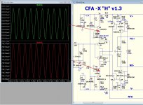
Plots show what signal is there.
OS
Attachments
I have a few questions about the caps.
How critical are the values? Are there some that have a range? Trying to learn something here. I look at C115-C124. They are listed as 22u. I see that they are basically in parallel. Is it critical that there be one per output or can it be taken care of with two or three if the totals add up? Are there other values that can be used?
Another question. I didn't have 68R for R113. Will 62R work? If so, does C114 change?
How critical is R103 at 1.8K? Can it be 2k or 1.5K? If so are there other changes that need to be made?
Thanks, Terry
-The 22u/100V 'ers can be 10-47u/100V. These are to individually decouple
OP collectors.
62 instead of the 68R will only result in <1% bias change , which WON'T be
thermally dependent.
On the other hand , the R103 = 1.8K is super critical. This is the primary
passive that determines the total Vbe coefficient.
R104/105 -Q103 is the driver "trim" for the vbe. This adds the driver
Vbe to the total co-efficient.
Depending on what driver/OP choices you make ... R103-105 can be
tweaked by +/- 20% (1k -1.5k , for example -R104-105) to match
device vbe.
Thimios has stated no issues with the posted values. 😎
OS
Waiting for this pcb,i did some listening test.
Os, i believe that spooky and symasui suvivor are very good amplifiers with deep and well controlling bass..It seems there isn't an amplifier ideal for all kind of musics..
Thimios.
Os, i believe that spooky and symasui suvivor are very good amplifiers with deep and well controlling bass..It seems there isn't an amplifier ideal for all kind of musics..
Thimios.
Last edited:
Waiting for this pcb,i did some listening test.
Os, i believe that spooky and symasui suvivor are very good amplifiers with deep and well controlling bass..It seems there isn't an amplifier ideal for all kind of musics..
Thimios.
Believe it or not , the "spooky/symasui" topologies are widely used in
many BJT subwoofer amps.
I believe this CFA-X/H will be my full range setup and one of my "badgers"
will end up as a "bassbadger".
OS
-The 22u/100V 'ers can be 10-47u/100V. These are to individually decouple
OP collectors.
62 instead of the 68R will only result in <1% bias change , which WON'T be
thermally dependent.
On the other hand , the R103 = 1.8K is super critical. This is the primary
passive that determines the total Vbe coefficient.
R104/105 -Q103 is the driver "trim" for the vbe. This adds the driver
Vbe to the total co-efficient.
Depending on what driver/OP choices you make ... R103-105 can be
tweaked by +/- 20% (1k -1.5k , for example -R104-105) to match
device vbe.
Thimios has stated no issues with the posted values. 😎
OS
Thanks OS,
A couple more questions if I may.
I have some 56uf caps. Can I use them for C111 and C113?
How about for C102 and C105?
Thanks, Terry
Thanks OS,
A couple more questions if I may.
I have some 56uf caps. Can I use them for C111 and C113?
How about for C102 and C105?
Thanks, Terry
C111/113 decouple the drivers. HK680 (reference amp) had 22u here.
Bigger the better - 56u is fine.
The multiplier output electro's (C102/105) can also be bigger since
we are reverse diode protected for the transistors 🙂 .
This was designed to be nearly "bombproof" ... only a few components
are critical.
OS
Hey OS thanks.
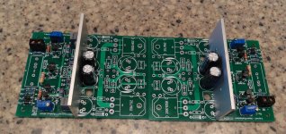
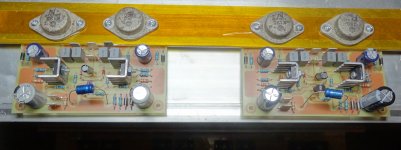
I went ahead and installed the 56uf in C111/113. I have to order caps for the output section anyway so I will keep 22u in C102/105 when they get here.
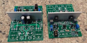
Here's a couple pics of my progress so far.
Blessings, Terry
I went ahead and installed the 56uf in C111/113. I have to order caps for the output section anyway so I will keep 22u in C102/105 when they get here.
Here's a couple pics of my progress so far.
Blessings, Terry
Attachments

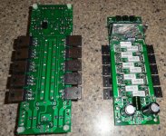
Terry,
That looks like some serious horsepower there. I hope you have something that actually needs to use anywhere near that much power, that should be able to burn up some voice-coils that's for sure.
That looks like some serious horsepower there. I hope you have something that actually needs to use anywhere near that much power, that should be able to burn up some voice-coils that's for sure.
Hey OS thanks.
I went ahead and installed the 56uf in C111/113. I have to order caps for the output section anyway so I will keep 22u in C102/105 when they get here.
Here's a couple pics of my progress so far.
Blessings, Terry
They look nice. Good work.
Thanks Guys.
I don't really "need" that much power. I have lots of "big" amps already including a full on PS system if I really need to get someone's attention. The idea here is to have the back end to handle just about any front end I care to throw at it. I can always turn it down and hopefully, this OPS will work well on lower rails if I want to try a lower voltage front end.
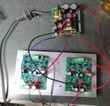
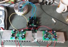
I threw together the two VSSA boards I got from Jason. Just need a few caps to finish them off. Placing an order now for the remaining parts I'll need to finish all four boards. Hopefully next week I'll have it all playing music. 😀
Maybe by the we'll have some Gerbers for some of these other amps so I can get some boards and part ordered for them. Looks like this could give me projects for some time to come.
Blessings, Terry
I don't really "need" that much power. I have lots of "big" amps already including a full on PS system if I really need to get someone's attention. The idea here is to have the back end to handle just about any front end I care to throw at it. I can always turn it down and hopefully, this OPS will work well on lower rails if I want to try a lower voltage front end.
I threw together the two VSSA boards I got from Jason. Just need a few caps to finish them off. Placing an order now for the remaining parts I'll need to finish all four boards. Hopefully next week I'll have it all playing music. 😀
Maybe by the we'll have some Gerbers for some of these other amps so I can get some boards and part ordered for them. Looks like this could give me projects for some time to come.
Blessings, Terry
Attachments
CFA vs. VFA "Rumble" Capacitive Loads.
Are there any technical reasons why CFA or VFA would have greater stability or superior sound when driving a large capacitive load like an electrostatic speaker or large Capacitor value in a filter?
Are there any technical reasons why CFA or VFA would have greater stability or superior sound when driving a large capacitive load like an electrostatic speaker or large Capacitor value in a filter?
Terry,
If you build these things so fast you will run out of projects fast! What is the difference between the thru hole VSSA amp you are putting together and the surface mount VSSA amps I have that came from Lazy Cat? I assume you are only using a section of those boards if they are only for the input section but if you built the entire board do they use lateral output devices?
If you build these things so fast you will run out of projects fast! What is the difference between the thru hole VSSA amp you are putting together and the surface mount VSSA amps I have that came from Lazy Cat? I assume you are only using a section of those boards if they are only for the input section but if you built the entire board do they use lateral output devices?
Hey OS thanks.
I went ahead and installed the 56uf in C111/113. I have to order caps for the output section anyway so I will keep 22u in C102/105 when they get here.
Here's a couple pics of my progress so far.
Blessings, Terry
Wow -very nice build! Those 'Slewmasters' look very good!
🙂
Terry,
If you build these things so fast you will run out of projects fast! What is the difference between the thru hole VSSA amp you are putting together and the surface mount VSSA amps I have that came from Lazy Cat? I assume you are only using a section of those boards if they are only for the input section but if you built the entire board do they use lateral output devices?
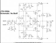
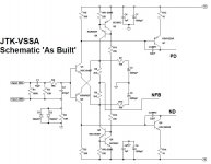
Hey Kind,
Yes, I am just using the front part of the circuit. I'll attach both the full schematic and the portion I am using for this. I have built the Peeceebee with TO-3 laterals, designed by Jason. Then I built the PMI through-hole version and then Jason's CCS version that these boards are designed for. I haven't heard the Cat's surface mount boards so I can't really compare them but the three that I have sound all but identical to each other.
I'm looking forward to comparing this version to them.
Hey Andrew,
Thanks for the compliment. Thanks for inspiring OS to start this thread. I'll get around to the CFA-XH before long.
Blessings, Terry
Attachments
Last edited:
Terry, very neat and tidy work - impressive. I will be following in your footsteps once I receive my Slewmaster and VSSA boards.
Terry,
I'll have to get out LC's schematic and compare the circuit and see how they differ if at all except that LC's have a bunch of surface mount devices on them. They are tiny.
I'll have to get out LC's schematic and compare the circuit and see how they differ if at all except that LC's have a bunch of surface mount devices on them. They are tiny.
Terry, very neat and tidy work - impressive. I will be following in your footsteps once I receive my Slewmaster and VSSA boards.
Do let me know when they arrive, I'd expect you will have them sometime this week.
Terry,
I looking at the pics of your partial VSSA boards, do make sure the VAS heat sink material isn't touching any of the pads on the board. Just ensure there is clearance so nothing gets shorted, there doesn't appear to be any gap in the picture but that can be deceiving sometimes.
I looking at the pics of your partial VSSA boards, do make sure the VAS heat sink material isn't touching any of the pads on the board. Just ensure there is clearance so nothing gets shorted, there doesn't appear to be any gap in the picture but that can be deceiving sometimes.
- Home
- Amplifiers
- Solid State
- Slewmaster - CFA vs. VFA "Rumble"