CFA vs. VFA "Rumble" Capacitive Loads.
Are there any technical reasons why CFA or VFA would have greater stability or superior sound when driving a large capacitive load like an electrostatic speaker or large Capacitor value in a filter?
The OPS would determine that. What drives it (the IPS) would have no
effect.
(the "anal" version of that last statement) .... with a CFA , a highly capacitive
load (might) feed back to the IPS a signal with enough phase shift to
possibly cause some "ringing". I simulated some wild loads to come to this
statement. Short of a paralleled peizo tweeter array .. it is unlikely ...
but possible. Nothings perfect 😱 .
PS - VFA's are more resistant to load dependant FB ... they see only voltage.
😀😀
EDIT - when simulated (or actually run) on a typical 12db/oct X-over w/standard
dome tweeter/woofer ... no issue with either (vfa/cfa).
OS
Last edited:
Hey OS thanks.
I went ahead and installed the 56uf in C111/113. I have to order caps for the output section anyway so I will keep 22u in C102/105 when they get here.
Here's a couple pics of my progress so far.
Blessings, Terry
I like that "diamond plate" aluminum (for driver HS) ... you must have a lot of it.
All your amps are built "ram tough" 😀
OS
Wondering if the FetZilla can be used as IPS board
If you could get the drains of T2/3 to conduct 4.5 - 5+ ma ,they could drive
the "slew" OPS ... no issue. 🙂
OS
Terry,
I looking at the pics of your partial VSSA boards, do make sure the VAS heat sink material isn't touching any of the pads on the board. Just ensure there is clearance so nothing gets shorted, there doesn't appear to be any gap in the picture but that can be deceiving sometimes.
Hi Jason,
Yes I saw that. I repositioned the heatsink slightly so nothing can touch but I will likely wrap the bottom of the heatsink with kapton tape just for assurance.
Once I have built some of OS's ISP's these will likely become full VSSA's. They are a good learning tool right now though. I won't be surprised if this sounds really, really good.
Blessings, Terry
Hey OS thanks.
I went ahead and installed the 56uf in C111/113. I have to order caps for the output section anyway so I will keep 22u in C102/105 when they get here.
Here's a couple pics of my progress so far.
Blessings, Terry
Nice work Terry, it's so beautiful!
Thimios.
Hey OS thanks.
I went ahead and installed the 56uf in C111/113. I have to order caps for the output section anyway so I will keep 22u in C102/105 when they get here.
Here's a couple pics of my progress so far.
Blessings, Terry
Looking REAL hard at your photo's ... watch those optional R/C pads beneath
your "fat" driver heatsink. If they touch that heatsink (magic smoke") 😱
PS - I originally designed for a thin roof flashing type heatsink. The
oversized drivers are such overkill that they could run the output
section without a heatsink ... really.
(anal explanation) to-3P's have just a couple Celsius/W thermal
properties. At even a <4R load on the EF3 , their junctions would only heat up
<10C ... Most to-220's are 5-10 C/W , they might need small heatsinks.
OS
If you could get the drains of T2/3 to conduct 4.5 - 5+ ma ,they could drive
the "slew" OPS ... no issue. 🙂
OS
Maybe Hugh,lineup or Greg could answer that,me certainly not.
Thanks Guys.
I don't really "need" that much power. I have lots of "big" amps already including a full on PS system if I really need to get someone's attention. The idea here is to have the back end to handle just about any front end I care to throw at it. I can always turn it down and hopefully, this OPS will work well on lower rails if I want to try a lower voltage front end.
I threw together the two VSSA boards I got from Jason. Just need a few caps to finish them off. Placing an order now for the remaining parts I'll need to finish all four boards. Hopefully next week I'll have it all playing music. 😀
Maybe by the we'll have some Gerbers for some of these other amps so I can get some boards and part ordered for them. Looks like this could give me projects for some time to come.
Blessings, Terry
Does R21 get shorted by the pcb trace?
-RM
Does R21 get shorted by the pcb trace?
-RM
Are you referring to R21 on my VSSA boards, since there is no R21 on the OPS? The vias under R20 and R21 have caused some folks to ask, but no, there is no short. What you see are a couple of vias placed under the device bodies of R20 and R21.
Last edited:
Looking REAL hard at your photo's ... watch those optional R/C pads beneath
your "fat" driver heatsink. If they touch that heatsink (magic smoke") 😱
PS - I originally designed for a thin roof flashing type heatsink. The
oversized drivers are such overkill that they could run the output
section without a heatsink ... really.
(anal explanation) to-3P's have just a couple Celsius/W thermal
properties. At even a <4R load on the EF3 , their junctions would only heat up
<10C ... Most to-220's are 5-10 C/W , they might need small heatsinks.
OS
Hi OS,
Yes I see what you mean. What is the purpose of the CS-A & CS-B? Are there supposed to be caps there? I actually wanted the heatsink to rest on the pcb for support so I will cover those with Kapton tape. I didn't know how much heatsink you planned for those and I had some scrap diamond plate and thought it would pretty it up. 🙂 I like using the thick metal better than thin because I can tap it and not need a nut.
Is there a good way to to test these boards without having an ISP hooked up to it?
One more question. What is the reason for the jumpers at R114 and R115?
Thanks, Terry
Last edited:
CS-A and CS-B are for added optional compensation should it be needed. The drivers don't need much of a heat sink at all, just some thin sheet is all that is required to provide some thermal coupling. The jumpers allow a separate supply to feed the drivers, predrivers and the rest should someone want to use a boosted supply about 6-10V higher for that.
Putting two resistors in place, one from +V to PD and another from -V to ND will allow the OPS to be run at idle without an IPS. Use ohms law to determine the value of the Red based on the rail voltage and approximately 4.5mA of current. So for 70V about 15k would be suitable.
Putting two resistors in place, one from +V to PD and another from -V to ND will allow the OPS to be run at idle without an IPS. Use ohms law to determine the value of the Red based on the rail voltage and approximately 4.5mA of current. So for 70V about 15k would be suitable.
Thanks Jason,
I'll probably stick with the heatsinks I have since they are already done unless this is a problem. Does Q103 need to be attached to that heatsink?
To be clear, I would jump V+ to PD with a 15K resistor and the same with V- to ND and then feed V+ and V- with +-70V? Will this allow me to set the bias?
Thanks, Terry
I don't have my materials handy to reference but if that is the TO-126 right beside one of the drivers, then yes it is to be attached to the heatsink.
You are correct about the resistors (the 15k for testing with no IPS installed). I would dial the bias to the desired level with the boards on the heatsink and let it idle for a while. When installing an IPS I would dial the bias down just to ensure it doesn't change should the VAS current not be quite the same as provided by the resistors.
You are correct about the resistors (the 15k for testing with no IPS installed). I would dial the bias to the desired level with the boards on the heatsink and let it idle for a while. When installing an IPS I would dial the bias down just to ensure it doesn't change should the VAS current not be quite the same as provided by the resistors.
Perfect!
One more question. I have a couple different schematics for the OPS. One uses MJE340/350 for all the small transistors and the other uses KSC1381/KSA3503 for some and MJE340/450 the pre-drivers. Any advantage/disadvantage with using the MJE340/350 for all of them?
One more question. I have a couple different schematics for the OPS. One uses MJE340/350 for all the small transistors and the other uses KSC1381/KSA3503 for some and MJE340/450 the pre-drivers. Any advantage/disadvantage with using the MJE340/350 for all of them?
Attachments

Should be fine with the MJE devices. The capacitance multiplier might benefit from higher gain devices but should be fine as is. I have KSA1220A / KSC2690A in mine as both pre-driver and cap multiplier, seems fine with those so far.
Jason and OS,
Since I don't have any of the devices for any of the positions, besides 1% 1/4 watt resistors laying around and have to order all the parts are there any preferred devices that I can go by when I order from Mouser or DigiKey or whomever has the parts? I see so many different transistor numbers and types I don't have a clue which ones to order, just to grab a number out of the soup seems counter intuitive to me. Can someone post a bom with preferred devices so I can order them and preferably something that would be available later so I can stay with the same devices down the road? I see all the MJE and KSA and other devices and just don't know what to go by. I have no experience with picking devices and so would love some guidance here, from lets say best to not worst but perhaps less desirable or hard to find. I surely don't want to hunt down nos parts, that isn't something I think I want to get into. I see enough about phoney devices and Ebay sales and would rather deal with a legitimate supplier of parts.
Thanks,
Steven
Unless OS puts somethin up first I'll suggest some devices later. I don't have full access to resources at the moment but there will be no NOS, just common, available and reasonably priced parts. No worries, it won't be a full BOM but rather some suggestions.
Thanks Jason,
I can figure out something like a resistor or diode from the schematic unless there are specific types somewhere but not virtually nothing about transistors besides what they are and how they function. I think with the CFA-XH we no longer are using any leds that I have noticed as this is something I have never encountered to use in an audio circuit like you are all doing now instead of a simple diode in those places. That was definitely something new to me before all these forums.
ps. Let me know when you get that MoneyOrder, I want to make sure it gets to you.
Thanks Jason,
I can figure out something like a resistor or diode from the schematic unless there are specific types somewhere but not virtually nothing about transistors besides what they are and how they function. I think with the CFA-XH we no longer are using any leds that I have noticed as this is something I have never encountered to use in an audio circuit like you are all doing now instead of a simple diode in those places. That was definitely something new to me before all these forums.
ps. Let me know when you get that MoneyOrder, I want to make sure it gets to you.
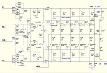
What ... no LED's 😱 . Of course we have leds !
ALL the "CFA-X -H" parts can be "junk box" (as long as they are proper
voltage and Ic).
The bom will be stupid simple -
1. ALL to-92's = KSA992/KSC1845
2. The VAS cascode TO-126's = KSA1381/KSC3503 "E" grade.
LED's = 2 plain red + 2 UV/blue (or even green)
The electro's will be 2- 1000u @10-16V + 2 100u 25-35v.
12V Zeners , trimmers , 914 diodes ... all standard fare.
All the resistors are non-critical besides the 2-3w current FB ones.
You could fit the schema/bom on a single index card 😎 .
Now to elaborate on the led's ... why not plain diodes ?
LED's seem to have just the right negative Vf /temp. to cancel
both the IP pair and Hawksford Vbe's .... they look good , will
confirm that your VAS/CCS's are operational ... and they are cheap.
I'm running them at 1/10th ( If) , 1.5ma red - 2.7ma blue/uv... they
will last 250K hours MTBF.
OS
- Home
- Amplifiers
- Solid State
- Slewmaster - CFA vs. VFA "Rumble"