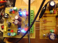
G2 on OPS not connected yet
this pict from post #2072
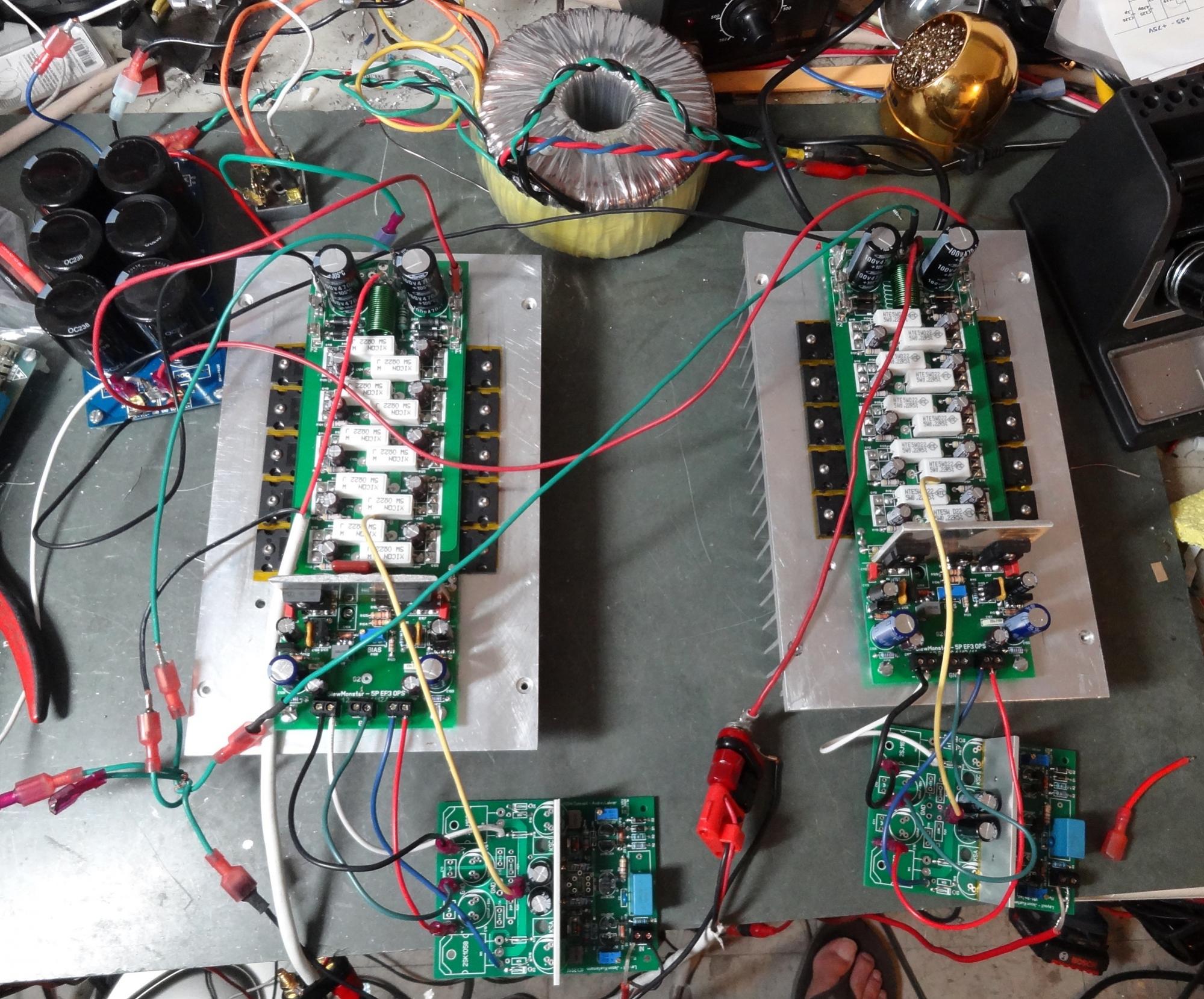
I see your G2 on OPS(near the terminal block) board is not connected anywhere yet...
There are two or three G2 on the OPS board, maybe you only connected the one near the rails tabs,
there is one G2 pad "free" that must be connected to the one near the terminal block
That should be connected to star ground if not then tour IPS is floating... 😱
Hi Terry,I pulled the IPS and installed 18K resistors across
....
That's where I measured. I will check it again.
this pict from post #2072
I see your G2 on OPS(near the terminal block) board is not connected anywhere yet...
There are two or three G2 on the OPS board, maybe you only connected the one near the rails tabs,
there is one G2 pad "free" that must be connected to the one near the terminal block
That should be connected to star ground if not then tour IPS is floating... 😱
Last edited:
Terry, I haven't juiced mine up to 70V yet, just up to 45v rails so far. I wonder if the higher rails are revealing something. However with your latest comments about the heat without the IPS then maybe the IPS is not the issue. You did put in the optional CSA and CSB that should help quell local instabilities. I'm very curious to look into this further. I will have to cobble together my planned 80V power supply and see if the behaviour changes.
Hi Terry,
this pict from post #2072
I see your G2 on OPS board is not connected anywhere yet...
That should be connected to star ground if not then tour IPS is floating... 😱
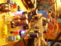
Hmm, did you ensure the G2 at both ends of the OPS were connected? I used a wire under the board but I don't see any evidence of the pads having been used.
Hi Guys,
Thanks for the suggestions and kind help. You are correct that in the picture, I didn't have the grounds connected on both ends of the board. I didn't see that instruction. I did connect it to star after thimios mentioned it in post 2105. I haven't installed a jumper on the board yet but I did attach both grounds to the star. Hopefully Jason will have time to hit his boards with some higher rails and see if he has a similar issue. I don't want to keep swapping parts willy nilly. It's too hard on the boards. I will take this time to install those long jumpers.
Thanks, Terry
Calculating heat sinks
transistor C/W table ... above.
The slew drivers are at 2w , the tables show just a few C/W with a
minimal heatsink on a to-3P device.
We should be running cool. Even the OP's on the main heatsink.
Higher rails will at most double the wattage but this would add just
a few C to the HS temp.
Raising the driver Re to 100R (like the HK680) would just drop
the drivers to 1W ... for just a small temp. reduction.
1W - 2W is minor ... as far as temperature. The HK to-220
drivers have NO heatsink - just get warm when I abuse the
amp.
OS
Hi OS,
Please build the boards that Jason sent you so we can see what is going on here.
Thanks, Terry
Please build the boards that Jason sent you so we can see what is going on here.
Thanks, Terry
Hi OS,
Please build the boards that Jason sent you so we can see what is going on here.
Thanks, Terry
I wish ... 🙁 I have to move 1400 miles away. I can't afford NY.
(1/2 my rent is the landlord's taxes) 😡 .
I find nearly all my DIY stuff as E-waste. It would truly come
down to food vs. DIY.
I'm packing now ... I might not be around between 6/1 and 7/1.
OS
I test mine on lower rails tomorrow and see if the drivers are still hot. I may try throwing a higher value in R113 just to see what happens. I can change out the drivers for something else but according to your figures, these devices should work.
Thanks again, Terry
Thanks again, Terry
You can run R113 as high as 220R - I simulated 150R ... all is spec.
This will run the drivers at just 7ma.
When you said the oscillation stopped as you "fiddled" with the input ,
I should of realized you had no ground.
Actually , I'm surprised everything survived. I "floated a ground" and
let "magic smoke" out 😱 .
PS - I did this modular OPS/IPS thing before ...."supersym" thread.
Built a DX amp , the badger , symasym ,and the hawksford luxman on a EF2 8 device OPS.
So , I have the "real world experience" ....
OS
I test mine on lower rails tomorrow and see if the drivers are still hot. I may try throwing a higher value in R113 just to see what happens. I can change out the drivers for something else but according to your figures, these devices should work.
Thanks again, Terry
The large drivers have 4-500Cob , the typical 15032/33 drivers used so often
have a large die and 300 Cob.
So , the to-247 drivers do not differ from the typical DIYA driver.
Electrically , they are not too different.
When I do build mine , I'll also use TO-3p drivers ... but sanken low cob
to-3p outputs.
I will fabricate a bracket to hold a slightly larger finned e- waste
PC power supply heatsink ( a good source for the driver heatsink -
most PC PS's have 2 heatsinks inside).
I'll most likely will also use the ON MJL/NJW outputs (from mouser).
OS
Hello Still4given
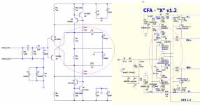
I note that the schematic JTK VSSA you showed has different feedback than original VSSA.
I put an attachment image for comparison. The small resistors on the original feedback configuration are connected in series with the css.
On the schema you posted the resistors are connected in series with fb caps which go to ground.
Maybe this causes the difference?
Jarno
Attachments
I wish ... 🙁 I have to move 1400 miles away. I can't afford NY.
(1/2 my rent is the landlord's taxes) 😡 .
I find nearly all my DIY stuff as E-waste. It would truly come
down to food vs. DIY.
I'm packing now ... I might not be around between 6/1 and 7/1.
OS
Unfortunately things are not well in Greece.Certainly taxes are increasing daily. Unemployment has reached 50% become unstoppable.
I personally Unemployed 2 years ago ...🙁
Hello Still4given
I note that the schematic JTK VSSA you showed has different feedback than original VSSA.
I put an attachment image for comparison. The small resistors on the original feedback configuration are connected in series with the css.
On the schema you posted the resistors are connected in series with fb caps which go to ground.
Maybe this causes the difference?
Jarno
Just a different gain. CFA-X is 26db , Jason's is mid 30's.
CFA's are pretty much stable over wide set of gains (vs. compensation).
More so than a VFA.
PS-Still4given has 129F/54C drivers , this is not REAL hot ...
as this is also the actual to-3p junction temp - 2C. Higher r113 +
one of them finned heatsinks would ensure for summer fun !!
I put the thinking cap on ... !! 80V would make quite a difference
as 45V would only be 35C at 1w.
PS - OHHH yeah , resistors are hooked to the CCS different ? I will simulate this !
OS
Last edited:
Unfortunately things are not well in Greece.Certainly taxes are increasing daily. Unemployment has reached 50% become unstoppable.
I personally Unemployed 2 years ago ...🙁
I share the pain ....
New york is "unstoppable" , would need to earn 100K here to live as well
in tennessee for 40K.
I built all my projects 3 years ago with extra $$ , all the extra $$ here go
to un-needed taxes/services that do nothing . 🙁
Do I need 3 police in every neighborhood to feel safe ? In tenn. ,1 police
for every 10 blocks was quite enough 😕 .
When I go back , I will build again.
But , NY has an excess of E-waste ... 10 trafo's - a whole box of parts
3 pair of audiophile speakers, 2 receivers/amps .... So, there are advantages.
Man ... they throw things away here !!!
OS
PS - OHHH yeah , resistors are hooked to the CCS different ? I will simulate this !
This does not change a thing (according to LT spice). 🙂
OS
Just a different gain. CFA-X is 26db , Jason's is mid 30's.
CFA's are pretty much stable over wide set of gains (vs. compensation).
More so than a VFA.
PS-Still4given has 129F/54C drivers , this is not REAL hot ...
as this is also the actual to-3p junction temp - 2C. Higher r113 +
one of them finned heatsinks would ensure for summer fun !!
I put the thinking cap on ... !! 80V would make quite a difference
as 45V would only be 35C at 1w.
OS
I'm sure the devices can probably survive this temperature but I wonder what the gain is? Are the drivers going to sound better at this bias? My biggest concern was that OS stated that these should only need a thin sheet of aluminum so when mine was so hot I naturally assumed I had done something wrong. Then I wondered why no one else had reported this problem but then I realized that only Jason has built one and he only tested at low voltage. Most of the amps I've built with multiple outputs have had the drivers mounted on the main heatsink. I'll try some different values in r113 tomorrow and report back.
Blessings, Terry
I'm sorry , I did not consider the max rail (80V).
The original HK680 (baseline OPS) is 55V with 150R. It stays cool.
I did expect the larger package to run cooler with it's die plate/larger
junction.
Actually , it IS running cooler with only 1-2C resistance between
die and "slug" (metal). A to-220 can run hotter and with 7+ C/w
resistance can FEEL cooler (but it's not) ... the die is 7+ degrees
hotter than the package !
A small to-92 can have a burnin' hot die at 50 C and the
plastic package could still be at 35c (15+C resistance).
You would get no performance "hit" by lowering the driver current ,
feel free to do so 😀 .
A note - using the 2sa1837/sc4793 pair would present a problem
if driving 5 pair OP (thimios). It's alright on my HK ... with only 2 pair
sanken OP ...
OS
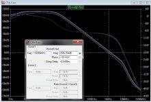
Oh yes it makes a difference if you degenerate the input pair with 47 ohm's or not.
open loop gain and phase margin is affected.
open loop gain and phase margin is affected.
Oh yes it makes a difference if you degenerate the input pair with 47 ohm's or not.
open loop gain and phase margin is affected.
Yes , gain (below 1) , UG point (below 2).
But at least with "CFA-X" , phase margin is sufficient with all
6 gains I stepped between @20 X and 40+ X (120R -20R).
Some VFA's don't have sufficient margin at higher UG points (unstable).
PS- I agree you need (something) - 47R .... "not" would raise UG way above a safe margin (poof ! 😀 ).
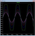
Also produced the same plot with both schema's from post 2131.
OS
Attachments
Last edited:
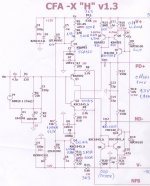
CFA-X V1.3
First fire ok. some first measurments.
Amplifier is alive and singing now.
Finally VFA is the winner for bass ,CFA is the winner for high!
THAT'S MY OPINION
PS I agree that cfa is a cheap ips but a suitable power supply for this ampl.isn't cheap at all.
My power supply with 22000uf/rail isn't quite for this because for low PSSR
Thimios.
Attachments
Last edited:
- Home
- Amplifiers
- Solid State
- Slewmaster - CFA vs. VFA "Rumble"