I'll take some measurements in the morning. I still think it is running too hot. Maybe I just need much larger heatsinks. I've been looking for an excuse to disassemble my Aleph-X. This may be the time.
Blessings, Terry
Blessings, Terry
Thank you very much, it is really report. That motivate me to look for high sr low hd design. Well, maybe try some cf, if vf attempts fail.
Yes, it will be interesting to compare measurements other than 200kHz square.
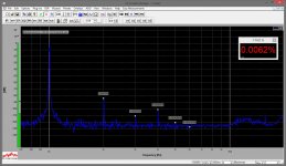
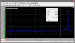
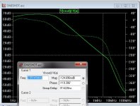
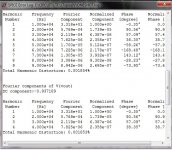
Hi all, just did THD / IMD measurements, using the recently-obtained Dr.Jordan's measurement system. See attached. Very cool harmonics distribution - most significant are the even ones (2, 4). 3 is much lower and 5 is practically not there...
12V RMS @ 8 Ohm resistive load
P.S. This is an addition to this post (CFA with GainWire input buffer)
Attachments
Last edited:
I'll take some measurements in the morning. I still think it is running too hot. Maybe I just need much larger heatsinks. I've been looking for an excuse to disassemble my Aleph-X. This may be the time.
Blessings, Terry
Check the output with scope for possible oscillation.
Otherwise calculate idle power dissipation and temp consistency with temp coeficient of your heatsink. 30 W constant idle power dissipation and 50 degC is quite normal for the size of your heatsink.
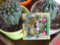
People asked "where is your 3D program"? ...
Thimios is my 3D program 😀 ..
They look nice, T ! These are the one's I will build.
PS - cool cacti ! Good climate for them ... I moving back to warmer
climes (tennessee) ... heck with "polar vortex's") ...
Edit - maybe a tad larger for the 100R CFB resistors ... I calculate >.3W
for them (worst case - they have lower V than the 2.7K's)
Thimios , make sure you jumper "a" to "a" for the input lifted ground to main IPS star.
OS
Last edited:
Do the TO-220 devices need a heatsink?
To keep them at the same thermal constant and super cool in 40c weather
it is preferred.
I've seen thimios test with none (no bad results). The "slew" IPS , at 4.5ma ...
is cooler than badgers or DX's. It's only running a EF3.
My HK680 just uses TO-92L VAS devices (no heatsink).
The heatsink should be just a scissor cut piece of (AL) roof flashing
25mm X 60mm ... that's all you need !
OS
Do the TO-220 devices need a heatsink?
These are TO-126 transistors and yes they need heatsink 😉
OK I sat down and took some measurements. This time I measured across two emitters and I'm getting 33mV. That's 75mA per pair or 375mA. Much closer to what I was reading. The voltage across R114 and R115 is 181mV or 38mA for the VAS and IPS. I have a 62R in R113 and I see 2V across that so that's 32mA across Q107/108. R110 reads 2.242V so 2.2mA there. I get 3.33V across PD+ and ND- if that means anything.
So if you guys can let me know if I'm in the ball park here I'd be grateful. I will lower the bias to 250 and see how that goes.
Blessings, Terry
So if you guys can let me know if I'm in the ball park here I'd be grateful. I will lower the bias to 250 and see how that goes.
Blessings, Terry
OK I sat down and took some measurements. This time I measured across two emitters and I'm getting 33mV. That's 75mA per pair or 375mA. Much closer to what I was reading. The voltage across R114 and R115 is 181mV or 38mA for the VAS and IPS. I have a 62R in R113 and I see 2V across that so that's 32mA across Q107/108. R110 reads 2.242V so 2.2mA there. I get 3.33V across PD+ and ND- if that means anything.
So if you guys can let me know if I'm in the ball park here I'd be grateful. I will lower the bias to 250 and see how that goes.
Blessings, Terry
Your within mV's of the simulated results.
3.4V = pd+/nd-
2.3v = R110
1.25v = R113
A typical EF3.
PS - on both my CFA IPS's , lower OP bias show lowest THD/best harmonics.
You could try even 35-45ma per OP.
My OEM even recommends 40ma in the service manual.
OS
Last edited:
do you mean this?People asked "where is your 3D program"? ...
Thimios is my 3D program 😀 ..
They look nice, T ! These are the one's I will build.
PS - cool cacti ! Good climate for them ... I moving back to warmer
climes (tennessee) ... heck with "polar vortex's") ...
Edit - maybe a tad larger for the 100R CFB resistors ... I calculate >.3W
for them (worst case - they have lower V than the 2.7K's)
Thimios , make sure you jumper "a" to "a" for the input lifted ground to main IPS star.
OS
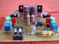
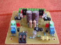
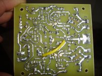
I haven't any 100R biger Watt this time.I think it's ok for first test.
Thank you for kind words,🙂
Attachments
Last edited:
do you mean this?
I haven't any 100R biger Watt this time.I think it's ok for first test.
Thank you for kind words,🙂
You read my mind 😎 ..
Very good !
OS
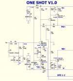
"ONE SHOT" CFA ....
Here is something different. This is what they SHOULD
be doing on the "CFA" thread !
(below) is a SINGLE CFB device driving a TMC beta enhanced VAS
with /current source.
I'm down to 20mv offset and 40ppm THD 20 with
just 5 devices.
I only just started refining CLG/UG (compensation).
😛😛 ...
OS
Here is something different. This is what they SHOULD
be doing on the "CFA" thread !
(below) is a SINGLE CFB device driving a TMC beta enhanced VAS
with /current source.
I'm down to 20mv offset and 40ppm THD 20 with
just 5 devices.
I only just started refining CLG/UG (compensation).
😛😛 ...
OS
Attachments
Oh oh another cfa😱Here is something different. This is what they SHOULD
be doing on the "CFA" thread !
(below) is a SINGLE CFB device driving a TMC beta enhanced VAS
with /current source.
I'm down to 20mv offset and 40ppm THD 20 with
just 5 devices.
I only just started refining CLG/UG (compensation).
😛😛 ...
OS
My god you can't stop.
I'm tired ,i will never built anything more

Last edited:
WOW !!
As expected , a single ended "badger/wolverine" VAS cancels
odd harmonics (below 1) ...
BUT , there is saturation on the enhanced VAS rail 🙁
(just like the badger -below 2).
CLG/UG seems to be almost a "hybrid" of a badger- CFA 😱 (below 3) .
Next is squarewave "abuse". (see if this sucker can "slew" !)
PS - I now am at <20ppm 20K !!
OS
Attachments

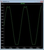
The "downside" ...
Slew sucks !
VAS CCS ( not having a symetrical current on demand) VAS
really slows things down.
About the same 50-70V/ uS ... same as the "badger".
Still , It proves a 5 device CFB powered "abomination"
can give PPM performance.
Look below -
H5-9 is only 1 part per billion. (1st 4 Vs. all 9) This circuit cancels out ALL
higher order components. 😱
OS
Attachments
Like the one I posted with the jfet front end... O.stripper You get inspired and make your own twist. 🙂 The Jfet version slew's better.
Here is something different. This is what they SHOULD
be doing on the "CFA" thread !
(below) is a SINGLE CFB device driving a TMC beta enhanced VAS
with /current source.
...
Cool! 😉
Aaaah - the poor man's variant of this one ...
Have had same "low" slew rate ...
OK I did some more testing. I lowered the bias and let the amp warm up. Everything looked good so I hooked it up and played some music through it. It held bias for a short while and then the bias shot up to 200mV across the emitters. No wonder the heatsinks were so hot. Looks like it is oscillating. It doesn't do it without something plugged into the inputs. Could use some help locating the problem.
The other issue is the drivers seem to be running too hot. I notice above the the simulation shows 1.25V across R113. I have 2V there. That's almost double the current. Should I replace the 62R with maybe 75R?
Thanks, Terry
The other issue is the drivers seem to be running too hot. I notice above the the simulation shows 1.25V across R113. I have 2V there. That's almost double the current. Should I replace the 62R with maybe 75R?
Thanks, Terry
- Home
- Amplifiers
- Solid State
- Slewmaster - CFA vs. VFA "Rumble"