Besides personal preferences what would or could anyone expect with a different artwork layout? Are you guys saying that a different layout would be superior or that it would just look different?
Besides personal preferences what would or could anyone expect with a different artwork layout? Are you guys saying that a different layout would be superior or that it would just look different?
Yes layout is very important, especially if double sided PCB FR4 2 mm thickness layout packed with SMD parts is compared to DIY layout. Huge difference!

Yes layout is very important, especially if double sided PCB FR4 2 mm thickness layout packed with SMD parts is compared to DIY layout. Huge difference!
Yes , we know smd (could) make for shorter paths and a more compact
footprint.
It would be interesting to compare these "apple and oranges" (SMD vs.
through-hole) !
Some of the more modern SMD amps (like the HK990) just perform
(slightly) better than the through hole "badger" or other amps (ASTX's
EF2 amp does just a few PPM in a real test).
The Badger is also "dead silent" (very low noise)- builders have said the
badger is much quieter than their OEM setups !
I used the same "anal" star grounding on
this "CFA-X-H" as the badger .... Combined with the OPS , we have "star
on star" 🙂 .
Also - High Z is kept away from low Z ...
There might be slight differences ... but with the same grounding and
"sectioning" of the layout - only the through -hole leads would add
to any degradation.
OS
I guess I should have been more specific. With the same components using thru hole devices on the same type of board, that was what I was really asking. Not a smd device board with very different ability to change the layout size. I don't know Alex so wasn't aware that he would design a smd version.
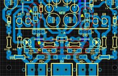
The PCB layout that Ostripper has afforded us should work as good as any. He has went out of his way to provide star grounding and 'finger room' between parts. It's easily made and it only measures 3 x 3 inches!
Sorry, I was just curious as to what Alex might change, if anything. I'm not really interested in SMD, mostly because all of my parts are through hole. I know I will, at some point, need to learn and understand SMD construction. I'm hoping that Jason will work out some Gerber files for this so I can have some boards made.
Blessings, Terry
Blessings, Terry
I'm planning on it but OS hasn't posed the sprint yet. If he doesn't I will just have to use the posted images as a guide and do it for myself from scratch.
I'm planning on it but OS hasn't posed the sprint yet. If he doesn't I will just have to use the posted images as a guide and do it for myself from scratch.
As long as I get a pair (pun intended). 😀
Below.... there it is. You can "proof it", too.
OS
Attachments
Thanks OS. I will get on this in the coming few days and hopefully have a layout in a similar style to the OPS.
Have you received any of my private communications?
Have you received any of my private communications?
I just responded to you.
Really good work. Between me , you , and thimios ... we can
have some "killer" projects !! 😎
OS
Really good work. Between me , you , and thimios ... we can
have some "killer" projects !! 😎
OS
With respect the the Csa/Csb locations on the OPS, could or should they be a set of pads to make it a Zobel for the base-collector or just leave it for capacitance only. I only ask since your notation on the schematic suggests values for an R and a C.
Last edited:
Thank you !
Here it is (package below) ... someone needs to build it. 😀
OS
Thanks uncle OS.

I was about to elaborate on both the compensation and led choices.
1. on the OPS , no need to embellish "csa/b" with a full zobel. I added
this option as a last resort for that yet to be encountered IPS / OPS
device combination that (may) exhibit some instability.
With this option , just about every EF3 local compensation method can
be implemented. (NO redesign needed - covered my ar$e 😀 ).
2. I'll elaborate on the "CFA-X" compensation.
Here I gave 3 options ....
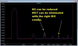
A. - straight miller comp - stuff "Cm1/2" with the 33pF caps.
slightly lower THD , but you get overshoot if you go too low (pF - value).
H3 is dominant , lowest THD at higher OPS bias.
B. The Hawksford "load" resistors - can be used with "A" or "C" (or not
at all). These load the cascode down , making for a more uniform
Z (impedance ) with regards to freq. and amplitude. A lower
value raises H2 and total THD.
C. "Lead/shunt" comp. This method will allow for the fastest slew ,
has slightly higher THD (H2) .... it is funny , a lower OPS bias
gives the lowest THD.
The different compensations of the hawksford seem to change how
it interacts with the EF3 OPS ... the change in optimum bias vs.
THD is notable.
The "fastest" is "C" ,with 150K/15-22pF (B-C below) .... I can
get this little "gem" to slew rail to rail in .15uS (600V/uS+) - EASY!
Another big "fallacy" is the need for massive current feedback. I
simulated with 120-150R/3.9K as CFB. This only made for 4ppm
increased THD (all biases). Slew could be increased by lowering
Cdom.
At these values, 1/2W-1W resisters could be safely used and all
the "current on demand" plus the other CFA attributes remain
constant.
This most basic CFA IPS is a definite "learning experience" , it
can show the limits (or drawbacks) when using this topology. 😎
THD harmonics can be "trimmed" with the proper compensations
(below 2).
OS
1. on the OPS , no need to embellish "csa/b" with a full zobel. I added
this option as a last resort for that yet to be encountered IPS / OPS
device combination that (may) exhibit some instability.
With this option , just about every EF3 local compensation method can
be implemented. (NO redesign needed - covered my ar$e 😀 ).
2. I'll elaborate on the "CFA-X" compensation.
Here I gave 3 options ....
A. - straight miller comp - stuff "Cm1/2" with the 33pF caps.
slightly lower THD , but you get overshoot if you go too low (pF - value).
H3 is dominant , lowest THD at higher OPS bias.
B. The Hawksford "load" resistors - can be used with "A" or "C" (or not
at all). These load the cascode down , making for a more uniform
Z (impedance ) with regards to freq. and amplitude. A lower
value raises H2 and total THD.
C. "Lead/shunt" comp. This method will allow for the fastest slew ,
has slightly higher THD (H2) .... it is funny , a lower OPS bias
gives the lowest THD.
The different compensations of the hawksford seem to change how
it interacts with the EF3 OPS ... the change in optimum bias vs.
THD is notable.
The "fastest" is "C" ,with 150K/15-22pF (B-C below) .... I can
get this little "gem" to slew rail to rail in .15uS (600V/uS+) - EASY!
Another big "fallacy" is the need for massive current feedback. I
simulated with 120-150R/3.9K as CFB. This only made for 4ppm
increased THD (all biases). Slew could be increased by lowering
Cdom.
At these values, 1/2W-1W resisters could be safely used and all
the "current on demand" plus the other CFA attributes remain
constant.
This most basic CFA IPS is a definite "learning experience" , it
can show the limits (or drawbacks) when using this topology. 😎
THD harmonics can be "trimmed" with the proper compensations
(below 2).
OS
Attachments
C. "Lead/shunt" comp. This method will allow for the fastest slew ,
has slightly higher THD (H2) .... it is funny , a lower OPS bias
gives the lowest THD.
😎
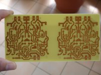
Getting ready for etching tonight 🙂
You may want to view my build progress in this link: SLEWMASTER Build
You may want to view my build progress in this link: SLEWMASTER Build
An externally hosted image should be here but it was not working when we last tested it.
Last edited:
jaagut
I can give you small advice, seem you are using non metalized film resistors (they just to be 0,2W) I have came across a failure of those resistors (burned one nice speaker), better of use metal film resistors 0,6W - they are more bullet-proof.
ostripper
I found that harmonics spectrum really does matter and can decribe the amp's sound character. But I do not know if keep them low allways mean beautiful sound. Harmonics are imho part of our every day ''life'' so maybe it would be possible to adjust them in the way that they will sing nice (not necessery neutral) ??
jaagut
I can give you small advice, seem you are using non metalized film resistors (they just to be 0,2W) I have came across a failure of those resistors (burned one nice speaker), better of use metal film resistors 0,6W - they are more bullet-proof.
ostripper
I found that harmonics spectrum really does matter and can decribe the amp's sound character. But I do not know if keep them low allways mean beautiful sound. Harmonics are imho part of our every day ''life'' so maybe it would be possible to adjust them in the way that they will sing nice (not necessery neutral) ??
Load the hell out of the VAS = <22k for R 17/18. H2 rises exponentially.
Some OEM's actually DO this !
OS
Load the hell out of the VAS = <22k for R 17/18. H2 rises exponentially.
Some OEM's actually DO this !
OS
It would be interesting to see report if someone try this. I tried some tricks to rise low h but the sound image was blurred.

- Home
- Amplifiers
- Solid State
- Slewmaster - CFA vs. VFA "Rumble"