Is this final version?
Yes , I also kept the ability to toner transfer it. (for you , my friend).
It is/was a joy to simulate/design/layout .... It will "fly/sing" very well.
OS
Thanks my friend🙂🙂Yes , I also kept the ability to toner transfer it. (for you , my friend).
It is/was a joy to simulate/design/layout .... It will "fly/sing" very well.
OS
That is really neat!
I like that compact board.
But I have a question: What does it look like with the outputs on it?
Daniel,
No outputs or VAS. This is IPS only. It attaches to the Slewmaster OPS board.
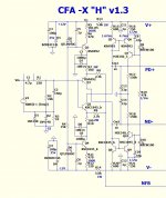
At high power levels the FB resistors see the full output. Music at normal levels likely wouldn't need 2W but a high power sine during testing will.
This is something to note that I failed to mention with the 'grafted' VSSA front end as well. The FB resistors were sized for lower rails, you might need to squeeze in a bigger unit or just be careful when testing that you don't burn one or both 2K2 at R8 and R9.
This is something to note that I failed to mention with the 'grafted' VSSA front end as well. The FB resistors were sized for lower rails, you might need to squeeze in a bigger unit or just be careful when testing that you don't burn one or both 2K2 at R8 and R9.
Last edited:
Why are the feedback resistors 2W? Seems hard to get well matched units in the 2W range.
3W would also work !
I use lower current feedback than most other CFA amps. 2w is prudent
as this IPS might be called upon for "ungodly" output swing.
As you might know .... this topology derives it's input pair current right
from the output (OPS).
Calculating for 100V p-p in just DC watts (ac wattage would be slightly less -
power factor/vs freq.) , the 20ma feedback signal would dissipate
about 1 W across R7-10.
So ...2 or 3 watt devices are especially required for R8/9 (2.7k). R7/10 (100R)
will dissipate less (could use 1 watt here).
Some will want even greater slew - R 8/9 can be 1.5K and 7/10 @ 68R.
Here you would be at 1-2W for all 4 resistors with 30+ma.
PS - you also could use 2 paralleled 6.8K-1w'ers for each 2.7K 🙂 .
OS
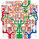
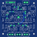
This one came out nice and easy 🙂 ...
Look over PCB vs. schema.
I'll post toner transfer "package" tomorrow.
I think this one is a "work of art".
OS
DON'T forget current measurements,that's useful for some resistor trim, as usual🙂
Last edited:
Thanks Guys,
That helps a lot. I was confused because the VSSA uses 1/4W resistors there. I'll stack four 1/2W, 10K resistors for each FB on the VSSA IPS I'm using, or would I be better off going with 5 each for 2K?
Thanks, Terry
That helps a lot. I was confused because the VSSA uses 1/4W resistors there. I'll stack four 1/2W, 10K resistors for each FB on the VSSA IPS I'm using, or would I be better off going with 5 each for 2K?
Thanks, Terry
Last edited:
I don't have time right at the moment to elaborate but I offer some detailed suggestions later when I can for the FB resistors.
Ostripper,
You've done an especially good job with this one. There is a simple elegance to it that I appreciate. Kudos to you!
You've done an especially good job with this one. There is a simple elegance to it that I appreciate. Kudos to you!
Ostripper,
You've done an especially good job with this one. There is a simple elegance to it that I appreciate. Kudos to you!
Thank you !
Here it is (package below) ... someone needs to build it. 😀
OS
Attachments
Excellent , well done 🙂 you are better day by day .
Regards Alex
But still not as good as you. 😉
(I concede)...
OS
Thank you !
Here it is (package below) ... someone needs to build it. 😀
OS

Tomorrow is a difficult day for me but i will try to find the time to make this alive.Thank you !
Here it is (package below) ... someone needs to build it. 😀
OS

Excellent , well done 🙂 you are better day by day .
Regards Alex
Wondering how your artwork would look like, mhmm.
Wondering how your artwork would look like, mhmm.
Come on Alex, give it a go.

- Home
- Amplifiers
- Solid State
- Slewmaster - CFA vs. VFA "Rumble"